What we'll do
- See what an Arduino is and what sits where on the board.
- Pick between the Uno, Nano and Mega.
- Install the Arduino IDE and upload the first sketch (Blink).
- Change the blink timing ourselves on a virtual Uno.
- Wire an external LED and a button: our first circuit.
Why it's useful: a robot car, a radar or a smart greenhouse all start the same way. By the end you can switch an LED with code and read a button, and every other project builds on that.
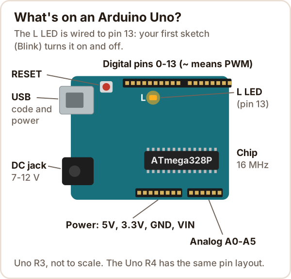
What is Arduino?
Arduino is an open-source electronics board with a small computer (a microcontroller) on it that you program from your computer over USB. The most common one is the Arduino Uno, built around the ATmega328P chip.
| Arduino Uno R3 | Value |
|---|---|
| Chip | ATmega328P, 16 MHz |
| Program memory | 32 KB (0.5 KB used by the bootloader) |
| Operating voltage | 5 V |
| Pins | 14 digital (6 with PWM), 6 analog inputs |
| Current per pin | 20 mA |
| Power | USB or DC jack (7-12 V recommended) |
What is Arduino used for, and how does it work?
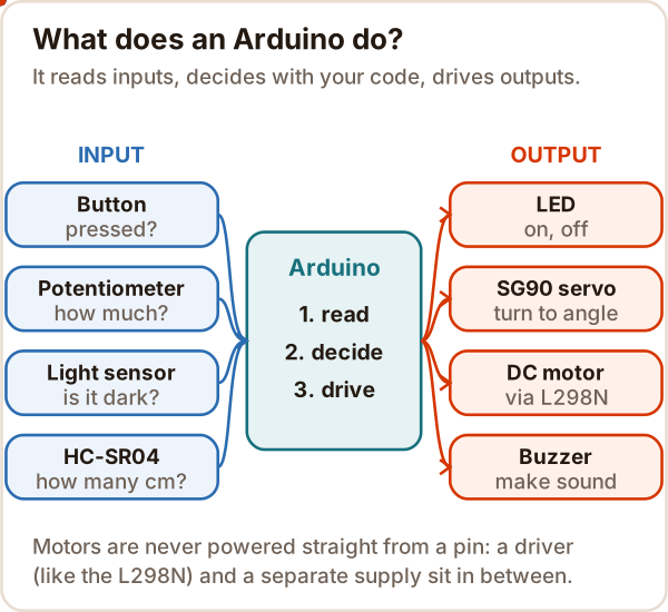
An Arduino reads inputs, decides what to do with the code you uploaded, and drives outputs. Every sketch has two parts:
setup()runs once when the board starts. You set up the pins here.loop()then repeats forever. The real work happens here.
What can you build with it?
- Obstacle-avoiding robot car: an HC-SR04 distance sensor and an L298N motor driver.
- Radar: a servo motor sweeps an HC-SR04 and the distances are drawn on screen.
- Line follower, smart greenhouse (measure soil moisture, run a pump), parking sensor, electronic dice.
Arduino boards: Uno vs Nano vs Mega
| Board | Chip | Digital / PWM | Analog | When? |
|---|---|---|---|---|
| Uno R3 | ATmega328P, 16 MHz | 14 / 6 | 6 | First board; most examples assume it |
| Uno R4 Minima / WiFi | Renesas RA4M1, 48 MHz | 14 / 6 | 6 | Faster, 256 KB memory, USB-C. The WiFi version adds Wi-Fi, Bluetooth and a 12×8 LED matrix |
| Nano | ATmega328, 16 MHz | 14 / 6 | 8 | Small builds; 45×18 mm, plugs into a breadboard |
| Mega 2560 | ATmega2560, 16 MHz | 54 / 15 | 16 | Big projects that need lots of pins |
Uno vs Nano: same chip, same code. The Nano is tiny, sits right on a breadboard, has no DC jack and has 2 extra analog inputs.
Uno R4 note: draw at most 8 mA from an R4 pin (20 mA on the R3). Still use a resistor with an LED, and never drive a motor from a pin.
Arduino Uno pinout
| Pin | What it does |
|---|---|
| 0-13 digital | Write or read HIGH (5 V) or LOW (0 V). 0 and 1 are the serial lines (RX/TX) |
| ~3, 5, 6, 9, 10, 11 | PWM: analogWrite() for LED brightness, motor speed |
| A0-A5 | analogRead() turns 0-5 V into a number from 0 to 1023 |
| 5V, 3.3V, GND | Power for sensors; GND is the common negative |
| VIN | External power input (same line as the DC jack) |
| RESET | Restarts the program, does not erase it |
On the Pinout tab of the virtual Uno below you can tap each group for a short explanation.
Installing the Arduino IDE and uploading code
Download the Arduino IDE from arduino.cc/en/software. IDE 2 runs on Windows 10 or newer (64-bit), macOS 10.15 or newer, and 64-bit Linux. If you'd rather not install anything, the Arduino Cloud Editor runs in the browser.
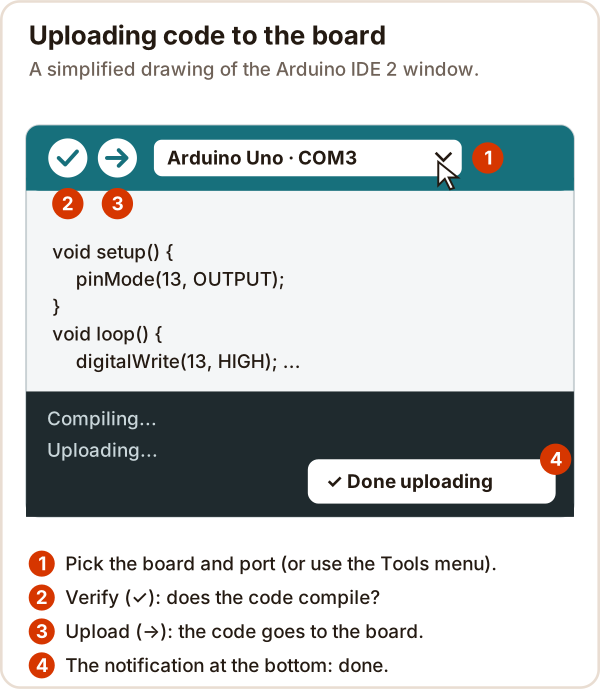
- Plug the board in with a USB cable (USB-B on the Uno R3, USB-C on the R4).
- Pick Arduino Uno and its port from the drop-down at the top. If it's not there, use Tools > Board and Tools > Port.
- Click Verify (✓) to check that the code compiles.
- Click Upload (→). When the notification appears at the bottom right, the code is running on the board.
On Windows the port looks like COM3; on Linux, like /dev/ttyACM0.
Arduino lesson 1: blink an LED
Everyone's first sketch: it blinks the on-board L LED (pin 13) once a second. You can also open it from File > Examples > 01.Basics > Blink.
// Blink: the on-board L LED (pin 13) blinks once a second
void setup() {
  pinMode(LED_BUILTIN, OUTPUT);     // runs once: make the pin an output
}

void loop() {                       // repeats forever
  digitalWrite(LED_BUILTIN, HIGH);  // on (5 V)
  delay(1000);                      // wait 1000 ms = 1 s
  digitalWrite(LED_BUILTIN, LOW);   // off (0 V)
  delay(1000);
}
On the Uno, LED_BUILTIN means 13. delay() takes milliseconds, and the board does nothing else while it waits.
Try it: the virtual Uno
Set the on time to 200 ms and the off time to 800 ms; then move the LED to pin 8, pick 3 times and watch how the code changes.
This is an interactive virtual Uno: change the pin and timing of the Blink sketch and watch the LED on a drawn Arduino Uno blink with exactly that timing, with a HIGH/LOW timing chart and a tappable pinout. It needs JavaScript. If it didn't load, the Blink code and the pin table above cover the same ground.
Wiring an external LED: why the resistor?
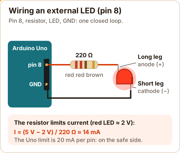
The resistor limits the current through the LED. Without it, the LED can damage itself and the pin. With 220 Ω the current is about 14 mA. To read the color bands, see the resistor color code guide.
// External LED: pin 8 -> 220 Ω -> LED long leg -> LED short leg -> GND
const int LED_PIN = 8;

void setup() {
  pinMode(LED_PIN, OUTPUT);
}

void loop() {
  digitalWrite(LED_PIN, HIGH);
  delay(200);                // short on
  digitalWrite(LED_PIN, LOW);
  delay(800);                // long off
}
Reading a button
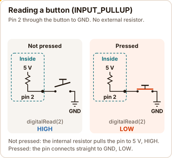
One button leg goes to pin 2, the other to GND. INPUT_PULLUP turns on a resistor inside the board, so no external one is needed. Note that a pressed button reads LOW.
// Button: pin 2 -> button -> GND. Press it and the L LED (pin 13) turns on.
const int BUTTON = 2;

void setup() {
  pinMode(BUTTON, INPUT_PULLUP);    // internal resistor pulls the pin to 5 V
  pinMode(LED_BUILTIN, OUTPUT);
}

void loop() {
  if (digitalRead(BUTTON) == LOW) { // pressed: the pin is tied to GND
    digitalWrite(LED_BUILTIN, HIGH);
  } else {
    digitalWrite(LED_BUILTIN, LOW);
  }
}
How to learn Arduino
- Blink: change the timing, add an external LED.
- Button: learn to read an input.
- Analog:
analogRead()with a potentiometer,analogWrite()for LED brightness. - Motion: a servo, then a DC motor through a driver.
- Project: combine them into a robot car or a radar.
Common mistakes
| Symptom | Cause | Fix |
|---|---|---|
| The board isn't in the port list | Charge-only cable; some compatible boards need a driver | Try a data cable; install the driver for boards with a CH340 chip |
| "Permission denied" on Linux | No serial port permission | Add your user to the dialout group |
| Upload fails | Wrong board or port; something on pins 0-1 | Check board and port, free pins 0 and 1 |
| A Nano won't take uploads | Old bootloader | Tools > Processor: ATmega328P (Old Bootloader) |
| External LED stays dark | LED is backwards | Long leg toward the resistor (pin), short leg to GND |
| The button "presses itself" | The pin is floating | Use INPUT_PULLUP |
expected ';' error |
Missing ; at the end of a line |
Look at the line just above the one it points to |
Sources
Accessed: 17 October 2026
- Arduino, UNO R3 tech specs: 5 V, 7-12 V, 20 mA per pin, 50 mA from the 3.3V pin, 32 KB memory, LED_BUILTIN 13.
- Arduino Docs, UNO R3 and its datasheet (A000066): pin table, A4/A5 I2C.
- Arduino Docs, UNO R4 Minima datasheet: RA4M1 48 MHz, 256 KB, 6-24 V, 8 mA per pin.
- Arduino Docs, UNO R4 WiFi: ESP32-S3, 12×8 LED matrix.
- Arduino Docs, Nano and Mega 2560: size, pin counts.
- Arduino Docs, Blink: 220 Ω, 1.8-2.2 V for a red LED.
- Arduino Docs, analogWrite and analogRead: PWM pins, 490/980 Hz, 0-1023.
- Arduino Docs, Uploading a sketch with IDE 2 and installing IDE 2: steps, system requirements, Linux port permission.
- Arduino Docs, Button: pull-up resistor, floating input.