What we'll do
- Look inside a breadboard and see which holes connect to which.
- Use the + and − power rails the right way.
- Build first circuits with an LED, a resistor and a button.
- Find and fix the 5 most common mistakes on a virtual breadboard.
- See how to measure current on a breadboard.
Why it's useful: a breadboard lets you build, pull apart and rebuild circuits without soldering. Most circuits that "just don't work" come down to one thing: not knowing which holes are connected inside.
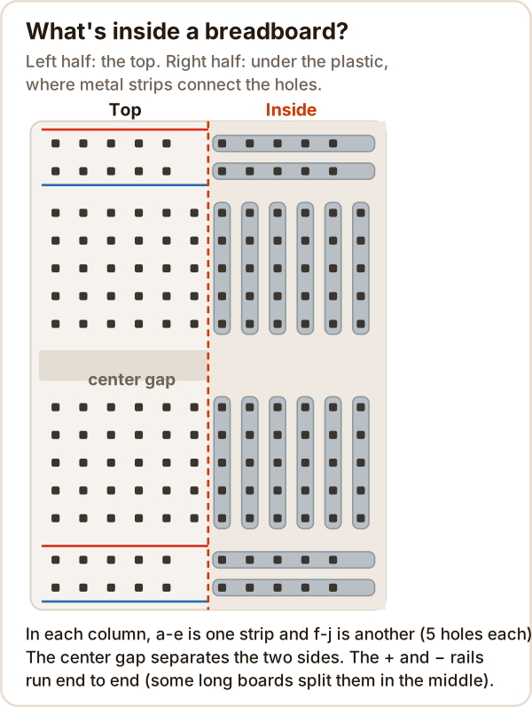
What is a breadboard and what is it used for?
A breadboard is a board full of holes for building circuits without solder. You push a leg into a hole and metal spring clips inside both hold it and connect it. The holes are 2.54 mm (0.1 in) apart, so LEDs, resistors, chips and an Arduino Nano plug straight in.
| Size | Holes | Layout |
|---|---|---|
| Mini | 170 | 17 columns × 10 holes, usually no power rails |
| Half | 400 | 30 columns × 10 holes + 4 rails × 25 |
| Full | 830 | 63 columns × 10 holes + 4 rails × 50 |
How are the holes on a breadboard connected?
In each column, the 5 holes from a to e share one metal strip inside; f to j is a separate strip. The center gap splits the two sides. The rails on the edges are connected end to end.
- Two legs in the same strip are connected, just as if they touched.
- Neighboring columns (say 12 and 13) are not connected.
- The center gap exists so a chip (DIP) can sit across it with its two rows of legs kept apart.
Breadboard + and − (power rails)
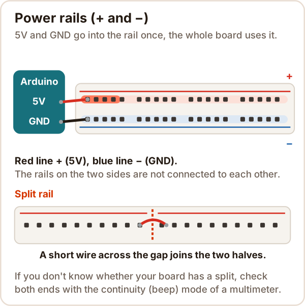
The long rows along the edges are the power rails: red-lined + (5 V) and blue-lined − (GND). You feed power into the rail once and every part takes it from there.
- Arduino 5V → + rail, GND → − rail.
- The rails on the two edges are not connected to each other; if you use both, join them with two short wires.
- Some long boards split the rails in the middle. If you're not sure, check continuity (the beep mode) with a multimeter.
Building an LED circuit on a breadboard
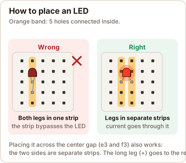
There's one rule: each part's two legs go into two different strips, and ends that should connect share a strip.
- Red wire: + rail → a5.
- 220 Ω resistor: c5 → c9. A resistor has no direction. To read its value, see the resistor color code.
- LED: long leg (anode) in e9, short leg (cathode) in e10. The LED rim is flat on the short-leg side.
- Black wire: a10 → − rail.
Current flows from the + rail through the resistor and the LED back to the − rail. With 5 V, a red LED (about 2 V) and 220 Ω, that's about (5 − 2) / 220 ≈ 14 mA.
Two LEDs in parallel: give each LED its own resistor, and connect each one between + and − on its own path.
Try it: a virtual breadboard
First tap a hole and see what lights up; then, on the Find the mistake tab, fix 5 circuits whose LED won't light.
This is an interactive half-size breadboard: tap any hole to light up every hole connected to it, then find and fix the faulty part in five LED circuits. It needs JavaScript. If it didn't load, the inside-view drawing and the steps above cover the same ground.
Wiring a button on a breadboard
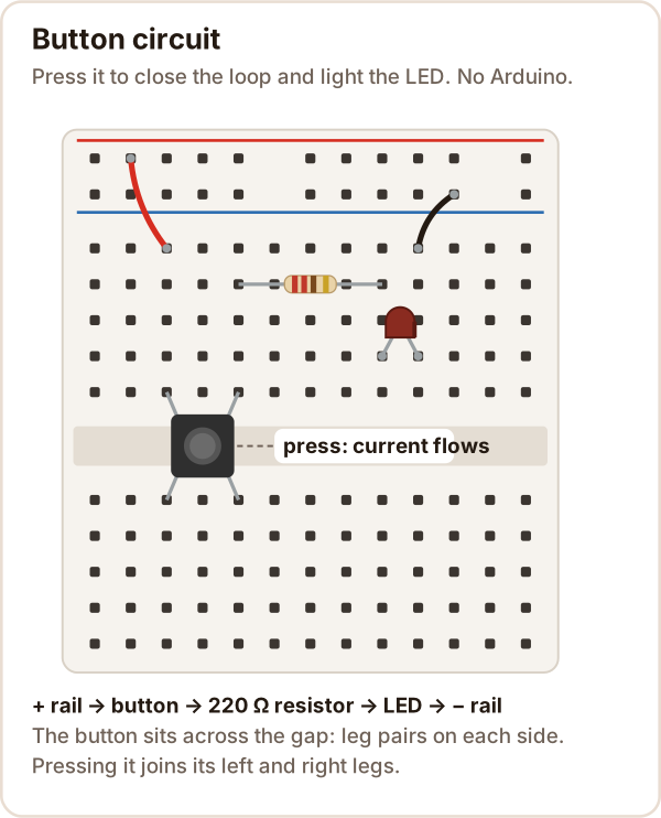
The button sits across the center gap; pressing it joins its left and right leg pairs and the LED lights. Four-leg buttons have their legs connected in pairs inside; if you're not sure which pair is which, check with the continuity mode of a multimeter.
To read the button with an Arduino, wire it to pin 2 and GND and use INPUT_PULLUP: the code is in What is Arduino.
Simple breadboard circuits to try
- LED + resistor: the circuit above, where everything starts.
- Button and LED: no Arduino, just the + and − rails.
- Two LEDs in parallel: one resistor each.
- Dimming with a potentiometer: a potentiometer in series with the 220 Ω dims the LED.
- Blink with an Arduino: pin 8 → resistor → LED → GND.
Mini breadboards and breadboard power modules
- Mini breadboard (170 holes): most have no power rails. Enough for a Nano or a single sensor.
- Power module: plugs onto the end of the board, over both rail pairs. It runs from a 6.5-12 V adapter or USB, and a jumper sets each rail pair to 5 V, 3.3 V or off. Check the jumper when a 3.3 V module is on the board.
Measuring current on a breadboard
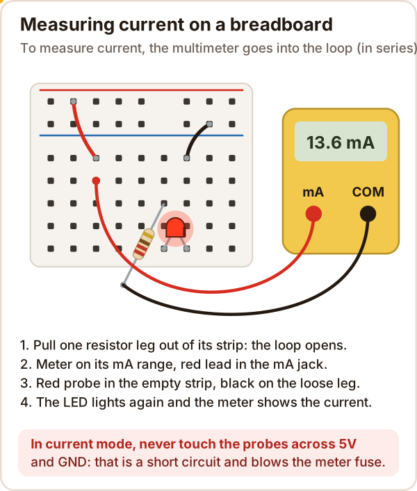
To measure current, the multimeter goes into the loop (in series): you open the circuit at one point and close the gap with the meter. To measure voltage you don't open anything; the probes just touch two points.
Common mistakes
| Symptom | Cause | Fix |
|---|---|---|
| LED dark, legs in the same column | Both legs in one strip | Move one leg to the next column |
| LED very bright and hot | Resistor in one strip, or missing | The resistor must bridge two strips |
| Everything looks right, LED dark | LED backwards | Long leg toward + |
| Half the board does nothing | Split rail, or the other edge has no power | Wire across the split or between the edges |
| The circuit cuts in and out | Leg not fully seated, thin leg | Straighten the leg, try another hole |
| The Arduino keeps resetting | + and − rails shorted by a wire | Unplug USB right away, check the wires |
Sources
Accessed: 17 October 2026
- SparkFun, How to Use a Breadboard: 5-clip strips, the center ravine and DIP chips, 0.1 in pitch, power rails, split rails, 400 and 170 tie-point boards.
- Adafruit, Full sized breadboard: 830 tie points, power rails on both sides.
- Handson Technology, MB102 breadboard power supply datasheet: 6.5-12 V or USB input, 0 V / 3.3 V / 5 V jumper per rail.
- SparkFun, How to Use a Multimeter: measuring current in series, fuse warning, continuity mode.
- Arduino Docs, Blink: 220 Ω resistor, 1.8-2.2 V for a red LED, long leg is the anode.