What we'll do
- Look inside a potentiometer and see how it works.
- Wire its three pins to an Arduino Uno and read the value.
- Turn a knob and watch the voltage, the analogRead value, and the LED and servo equivalents change live.
- Dim an LED with a pot, pick the right pot, and find a bad one with a multimeter.
Why it's useful: a pot is the easiest way to tell a robot "how much": speed, angle, brightness, a threshold. Once you know how to wire one, joysticks and many analog parts read the same way.
What is a potentiometer used for?
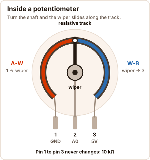
A potentiometer (pot for short) is a resistor you adjust by turning a shaft. It has three pins: two ends, and a middle pin connected to the sliding contact, the wiper.
- In everyday things: volume knobs, the inside of game controllers, small trim screws on circuit boards.
- In robotics: setting motor speed, servo angle or LED brightness by hand, and measuring the angle of an arm. Hobby servos have a pot inside that measures their position.
How does a potentiometer work?
A pot splits the voltage across its ends at the wiper. That is called a voltage divider.
- The resistance from pin 1 to pin 3 is fixed: always 10 kΩ on a 10 kΩ pot.
- Turning the shaft slides the wiper: A-W (pin 1 to middle) grows and W-B (middle to pin 3) shrinks. Their sum never changes.
- Put pin 1 on GND and pin 3 on 5 V, and the middle pin sits anywhere between 0 and 5 V.
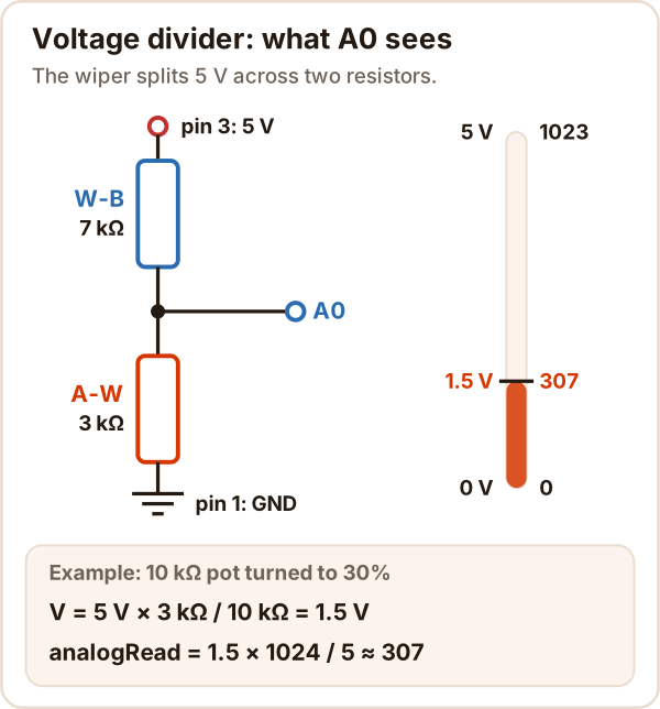
V(middle pin) = 5 V × A-W / (A-W + W-B)
Potentiometer pins: how do you wire one?
One rule: the two outer pins go to 5V and GND, the middle pin goes to whatever measures it.
| Pin | On an Arduino Uno |
|---|---|
| 1 (outer) | GND |
| 2 (middle, wiper) | A0: the voltage you measure |
| 3 (outer) | 5V |
- Swap the outer pins and nothing breaks; the knob just works in the other direction.
- Don't connect the middle pin to 5V or GND: at the end of travel there is no resistance left between 5V and GND, so you get a short circuit.
Reading a potentiometer with Arduino
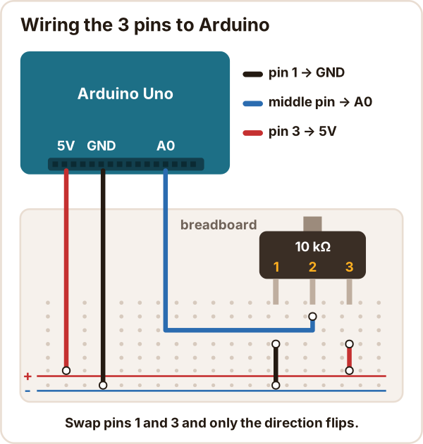
Put the three pins in three different breadboard columns; how to use a breadboard shows which holes are connected. Upload this sketch, open the Serial Monitor and turn the shaft:
// Read a potentiometer and print the value and voltage to the Serial Monitor.
// Wiring: pin 1 -> GND, middle pin -> A0, pin 3 -> 5V
const int POT_PIN = A0;

void setup() {
  Serial.begin(9600);                     // set the Serial Monitor to 9600 baud
}

void loop() {
  int value = analogRead(POT_PIN);        // 0 to 1023
  float volts = value * 5.0 / 1024.0;     // approximate voltage (5 V reference)
  Serial.print("Value: ");
  Serial.print(value);
  Serial.print("   Voltage: ");
  Serial.print(volts, 2);
  Serial.println(" V");
  delay(200);                             // 5 lines per second
}
- The Uno's analog input is 10-bit: 0 V reads 0 and 5 V reads 1023. One step is about 4.9 mV.
- A reading takes about 100 µs, so reading it every loop is fine.
- New to the Uno? Start with what is Arduino.
Try it yourself
Turn the knob, then press 3.3V pin and 100 kΩ and see which number changes and why.
This is a potentiometer knob you can turn: it shows the wiper position, the two resistances, the voltage at A0, the analogRead value and what that means for an LED and a servo. It needs JavaScript; if it didn't load, the voltage divider diagram above shows the same math.
The math is the formula from the ATmega328P datasheet: analogRead = V × 1024 / 5, capped at 1023. The log curve is a simple model.
Dimming an LED with a potentiometer
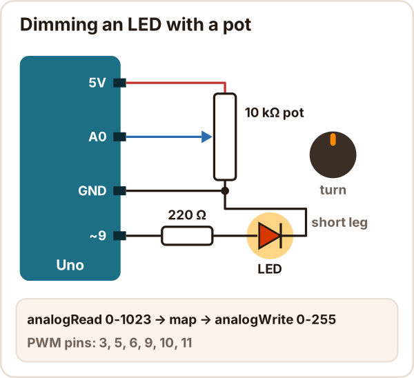
// Dim an LED with a potentiometer.
// Pot: pin 1 GND, middle pin A0, pin 3 5V.
// LED: pin 9 -> 220 ohm resistor -> LED long leg, LED short leg -> GND
const int POT_PIN = A0;
const int LED_PIN = 9;                    // a PWM pin (marked ~)

void setup() {
  pinMode(LED_PIN, OUTPUT);
}

void loop() {
  int value = analogRead(POT_PIN);                  // 0-1023
  int brightness = map(value, 0, 1023, 0, 255);     // scale to 0-255
  analogWrite(LED_PIN, brightness);                 // PWM sets the brightness
  delay(10);
}
analogReadgives 0-1023 andanalogWritewants 0-255.map()converts between them (integer math, it drops the fraction).- Use a pin marked ~. On the Uno the PWM pins are 3, 5, 6, 9, 10 and 11.
- A servo works the same way:
map(value, 0, 1023, 0, 180). More in servo motor basics.
Controlling DC motor speed with a potentiometer
Don't run the motor current through the pot. Small pots handle very little power (a Bourns PTV09 is rated 0.05 W), and motor current will overheat and ruin it.
The right way: pot → A0 → analogWrite → transistor or motor driver (such as an L298N) → motor.
- The LED sketch above works unchanged; pin 9 goes to the driver's speed (EN) input instead of the LED.
- The motor gets its own supply, with the grounds connected together.
Types of potentiometers: linear, log, trimpot
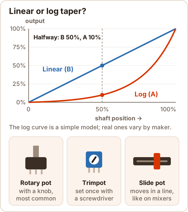
- Linear (B): resistance changes evenly as you turn. Pick this for Arduino.
B10Kon the body usually means "linear, 10 kΩ". - Log (A, audio taper): slow at first, then fast; made for volume knobs. Letter codes are not the same everywhere, so if in doubt, measure at the halfway point.
- Trimpot: a small board-mounted pot you set once with a screwdriver, like the threshold adjuster on sensor modules.
Why is 10 kΩ everywhere? The Uno's analog input is designed for sources of 10 kΩ or less. A 1 kΩ pot draws 5 mA from 5 V all the time, and a 100 kΩ pot can make readings drift a little.
How to test a potentiometer with a multimeter
Power off, and set the meter to resistance (Ω). How to use a multimeter covers picking the range.
- Pin 1 to pin 3: should be close to the marked value. Tolerance is wide: a ±20% 10 kΩ pot can read anywhere from 8 to 12 kΩ.
- Pin 1 to middle: turn the shaft slowly. The value should move smoothly from near zero to the full value.
- Signs of a bad pot: the value jumps, briefly shows open circuit (OL), or doesn't change at all. The track or wiper is worn, and on an Arduino the numbers jitter.
Common mistakes
| Symptom | Cause | Fix |
|---|---|---|
| Value wanders by itself | Middle pin not really in A0, input floating | Check the wire and the breadboard column |
| Always 0 or always 1023 | An outer pin is on A0, not the middle one | Move the middle pin to A0 |
| Tops out around 675 | Pin 3 on 3.3V while the Uno measures against 5 V | Move pin 3 to 5V |
| Goes the wrong way | Pins 1 and 3 swapped | Swap the outer pins or use map(v, 0, 1023, 255, 0) |
| Pot gets hot at the end, Uno resets | Middle pin wired to 5V or GND | Go back to the wiring table |
| LED lights but won't dim | LED on a non-PWM pin | Move it to a ~ pin such as 9 |
| Pot got hot, motor is weak | Motor current runs through the pot | Pot to A0 only; drive the motor with a driver |
Sources
Accessed: 17 October 2026
- Arduino, analogRead(): 10-bit, 0-1023, 4.9 mV steps on the Uno, about 100 µs, floating pins wander.
- Arduino, analogReference(): the default reference on 5 V boards is 5 V.
- Arduino, analogWrite() and map(): Uno PWM pins, 0-255, integer math.
- Arduino, AnalogInOutSerial example: pot on A0, LED on pin 9 through 220 Ω.
- Microchip, ATmega328P datasheet: ADC = Vin × 1024 / Vref; the ADC is designed for sources of 10 kΩ or less.
- Bourns, PTV09 datasheet: linear and audio tapers, ±20% tolerance, 0.05 W, 280° mechanical angle.
- Wikipedia, Potentiometer: taper letter codes are not standardized; what a "10% log" taper means.