What we'll do
- Get to know the display, the dial and the sockets of a multimeter.
- Learn what the dial symbols mean: DCV, ACV, DCA, Ω, hFE and more.
- Measure a battery, a resistor, a wire and an LED circuit: first on a virtual meter, then on a real one.
- Look at the most common mistakes (OL, a minus sign, a blown fuse) and what causes them.
Why it's useful: when your robot stops working, you can measure whether the problem is the battery, a wire or the circuit instead of guessing.
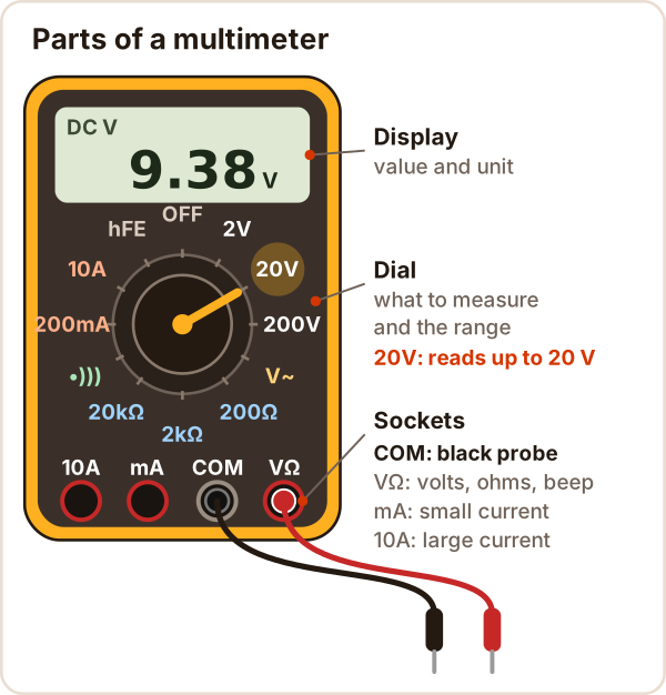
What is a multimeter and what is it used for?
A multimeter is a test tool that measures voltage (volts), current (amps) and resistance (ohms) in one device. In robotics it answers questions like these:
- Is the battery charged? Voltage
- Is a wire broken inside, is a solder joint making contact? Continuity
- Is this resistor the right value? Resistance
- How much current does the LED or motor draw? Current
Every example in this post is low voltage: batteries and 5 to 12 V circuits.
How to read a multimeter: the dial symbols
The dial picks what you measure and the range. The number next to a position is the largest value it can show: the 20V position reads up to 20 V.
| Symbol | Meaning | Used in robotics for |
|---|---|---|
| DCV | Direct (DC) voltage | Batteries, packs, the Arduino 5V pin |
| ACV (V~) | Alternating (AC) voltage | Wall outlets: not a student job |
| DCA | Direct current | Current drawn by an LED or motor |
| Ω | Resistance | Resistors, potentiometers, sensors |
| •))) | Continuity (beep) | Broken wires, short circuits |
| hFE | Transistor gain | A transistor plugs into the small socket on the meter |
| NCV | Non-contact voltage detection | Outlets and house wiring: an electrician's tool |
Sockets: the black probe always goes in COM. The red probe goes in VΩ for voltage, resistance and continuity, mA for small currents (up to 200 mA on many meters, fused) and 10A for large currents.
If the display shows OL (or just 1 on some meters), the value doesn't fit the range: go up one range. Autoranging meters pick the range for you.
How to use a multimeter in 4 steps
- Plug the black probe into COM.
- Plug the red probe in for the job: VΩ for voltage and resistance, mA for current (start with 10A if you have no idea how big the current is).
- Turn the dial to the measurement type and the smallest range that is above the value you expect.
- Touch the probes: in parallel for voltage (across two points), in series for current (break the circuit and go in the gap), and only on unpowered parts for resistance.
Try it: a virtual multimeter
Pick a task, then tap the dial positions and the sockets. Try the wrong settings too: the meter explains what happened.
This is a virtual multimeter you use by tapping: pick a task, turn the dial and plug the red probe into a socket. It needs JavaScript; if it didn't load, the pictures below show the same measurements.
The numbers come from a simple model, so a real meter will differ in the last digits. Try this: measure the 9 V battery on 2V first, then on 20V. In the LED task, pick Parallel and measure with the ammeter.
How to test a battery with a multimeter (9 V, AA, car battery)
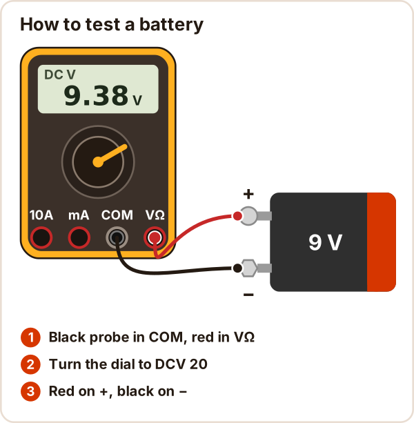
To test a battery, set the dial to DCV, touch the red probe to + and the black one to −.
| What you measure | Dial | Note |
|---|---|---|
| 1.5 V AA battery | DCV 2 (or 20) | About 1.1 V under load: nearly empty |
| 9 V battery | DCV 20 | Nominal voltage 9.0 V |
| 12 V car battery | DCV 20 | Fully charged after a 24 h rest: about 12.65 V |
- A no-load reading is only a rough guide. Energizer's alkaline handbook suggests measuring under load for 1 to 2 seconds (about 10 Ω for an AA); a fresh cell reads about 1.5 V that way.
- A lead-acid battery needs at least 4 hours of rest after charging before its voltage shows the real charge.
- The same way, you can measure between the 5V and GND pins of an Arduino.
Never touch a battery's terminals with the red probe in the mA or 10A socket: that is a short circuit, the leads heat up and the fuse blows.
How to measure resistance
Resistance is measured with the power off: the meter sends a small current from its own battery and works out the resistance.
- Set the dial to Ω, on the smallest range above the expected value (20k for 4.7 kΩ).
- Take the resistor out of the circuit, or lift at least one leg; otherwise the parts next to it get measured too.
- Touch the probes to both legs. Direction doesn't matter.
The reading should fall inside the tolerance of the color code. To read the colors: Resistor color code and calculator.
Continuity test: how to find a broken wire
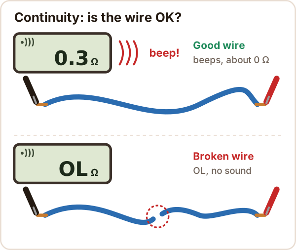
In the continuity position (•))) ) the meter beeps when the resistance between two points is very low. On the Fluke 114 to 117 meters, for example, the beeper turns on below 20 Ω and off above 250 Ω.
- Turn the circuit's power off and set the dial to •))).
- Touch the probes together: the meter should beep. If it doesn't, check the leads and the meter's battery.
- Touch both ends of the wire. A beep means it's good; OL and no sound means it's broken.
- On a long connection, hold one probe still and touch points along the way with the other (connector pins, solder joints, breadboard rows). The break is where the beep stops.
The same test finds shorts: with the power off, a meter that keeps beeping between 5V and GND means a short somewhere. A short beep at first is normal in a circuit with capacitors: the meter beeps while they charge.
How to measure current (amps) with a multimeter
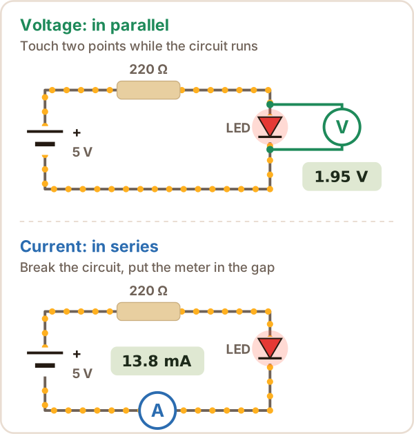
Current is measured in series: you break the circuit at one point and put the meter in the gap, so the current flows through the meter.
- Turn the power off and plug the red probe into mA. If you can't estimate the current, start with the 10A socket and the 10A position.
- Set the dial to 200mA (DCA).
- Break the circuit at one point (on a breadboard, just pull one jumper), touch the probes to the two open ends, then power up.
Example: 5 V, 220 Ω and a red LED. The LED takes about 2 V (Kingbright WP7113ID datasheet: typically 1.9 V at 10 mA), so about 3 V is left across the resistor: 3 V / 220 Ω ≈ 14 mA.
Never connect an ammeter in parallel. The current socket has almost zero resistance and shorts out whatever you touch. A motor's current rises a lot when it is loaded, so start motors on the 10A socket.
What are ACV, True RMS and CAT ratings?
- ACV (V~): voltage that keeps changing direction, like a wall outlet. Measuring wall outlets is not for students or robot teams; anything involving mains voltage is a job for an electrician. Robot projects almost never need ACV.
- True RMS: according to Fluke, an average-responding meter assumes a pure sine wave, while a true-RMS meter also reads distorted waveforms correctly. For batteries and DC circuits it makes no difference.
- CAT II, III, IV: under IEC 61010 these say where a meter can be used safely; in Fluke's definitions CAT II covers plug-in appliances, CAT III building distribution panels and CAT IV the utility connection.
Common mistakes
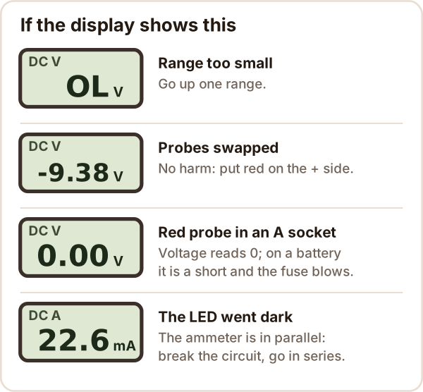
| What you see | Cause | Fix |
|---|---|---|
| OL or 1 | Range too small | Go up one range |
| Current always reads 0 | Red probe in VΩ, blown fuse, or meter not in series | mA socket, series connection, check the fuse |
| Odd resistance value | Part still in the circuit, or powered | Power off, lift one leg |
| No beep even with the probes touching | Meter battery dead or a broken lead | Check the battery and the leads |
If a fuse blows, replace it with one of the same rating: never put a 10 A fuse where a 200 mA fuse goes.
Sources
Accessed October 17, 2026
- SparkFun, How to Use a Multimeter: COM, mAVΩ and 10A sockets, series and parallel connection, OL, swapped probes, fuses.
- Fluke, IEC Category Ratings: Use the Right Tools for the Job: CAT II, III and IV definitions.
- Fluke, When Do You Actually Need a True-RMS Multimeter?: true-RMS versus average-responding meters.
- Fluke 114, 115, 116, 117 datasheet (PDF): continuity beeper thresholds.
- Energizer, Alkaline Handbook: no-load versus under-load battery testing, the 1.5 V and 1.1 V figures.
- Energizer, 522 (9 V) datasheet: 9.0 V nominal voltage.
- Battery University, BU-903: How to Measure State-of-charge: lead-acid rest voltage and rest time.
- Kingbright, WP7113ID datasheet: red LED forward voltage.