What we'll do
- Look inside a capacitor and see how it stores charge.
- Learn the types, the symbols, and how to read codes like 104.
- Watch a capacitor charge and discharge in a live lab and see τ = R·C for ourselves.
- Learn where capacitors go on a robot, how to test one and how to discharge it safely.
Why it's useful: an Arduino that resets when the motor starts, or a sensor reading that jitters, is very often fixed by one small capacitor in the right spot.
What is a capacitor?
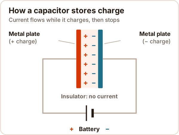
A capacitor is a two-legged component that stores electric charge for a short time: two conducting plates with an insulator between them.
Unlike a battery, it can't power anything for hours, but it charges and empties very quickly. That makes it good at filling voltage dips, filtering noise and timing things.
The unit is the farad (F). One farad is huge; on real circuits you'll see:
| Unit | Equals | Example |
|---|---|---|
| µF (microfarad) | 0.000001 F | Electrolytic: 10 µF, 100 µF, 1000 µF |
| nF (nanofarad) | 1/1000 of a µF | Ceramic: 100 nF (code 104) |
| pF (picofarad) | 1/1000 of a nF | Ceramic: 22 pF, 100 pF |
How does a capacitor work?
Connect it to a battery and positive charge builds up on one plate, negative on the other. No current crosses the insulator: current only flows in the wires while it charges, then stops. Remove the battery and the charge stays on the plates.
The stored charge is proportional to the voltage:
Q = C × V (charge = capacitance × voltage)
Physics class note: for a parallel-plate capacitor, C = ε × A / d. Bigger plates (A) mean more capacitance; a wider gap (d) means less; ε depends on the insulator.
Capacitor types and symbols
| Type | Polarity | Values | Where on a robot |
|---|---|---|---|
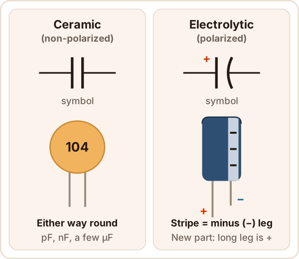
| Ceramic | None, fits either way | pF, nF, a few µF | 100 nF next to chips, across motor terminals |
| Electrolytic | Yes: striped leg is minus | µF up to thousands of µF | Power inputs, next to the motor driver |
An electrolytic also shows a voltage rating (for example 25 V). It must be well above the highest voltage in your circuit.
How to read capacitor codes: what is 104?
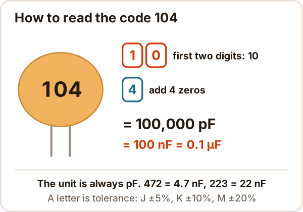
104 = 100 nF = 0.1 µF. The first two digits are the number, the third is how many zeros to add, and the unit is picofarads (pF).
| Code | In pF | Value |
|---|---|---|
| 101 | 100 pF | 100 pF |
| 472 | 4,700 pF | 4.7 nF |
| 223 | 22,000 pF | 22 nF |
| 104 | 100,000 pF | 100 nF = 0.1 µF |
| 105 | 1,000,000 pF | 1 µF |
Electrolytics just print the value ("100µF 16V"). A letter after a ceramic code is the tolerance: J ±5%, K ±10%, M ±20%.
Capacitor formulas: series and parallel
| What | Formula | Example |
|---|---|---|
| Charge | Q = C·V | 100 µF at 12 V → 1.2 mC |
| Energy | E = ½·C·V² | 100 µF at 12 V → 7.2 mJ |
| Time constant | τ = R·C | 10 kΩ, 100 µF → 1 s |
| Parallel | C = C1 + C2 | 100 µF and 47 µF → 147 µF |
| Series | 1/C = 1/C1 + 1/C2 | 10 µF and 10 µF → 5 µF |
It's the opposite of resistors: resistors add up in series, capacitors add up in parallel (resistor color code).
Charging and discharging: what does τ = R·C mean?
Charged through a resistor, a capacitor's voltage rises fast at first, then slowly. Every τ = R·C closes 63% of the remaining gap: 63% after 1τ, 99.3% after 5τ. When discharging, 37% of the voltage is left after 1τ.
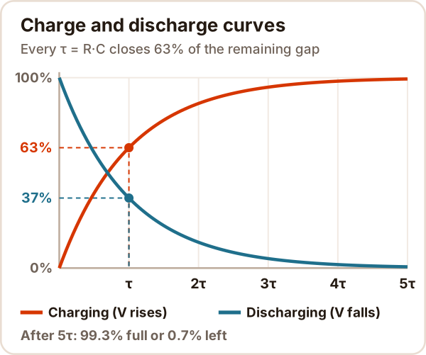
Try it: with 10 kΩ and 100 µF, press Charge; the curve hits 63% in one second. Then press Discharge and watch the LED. Make R or C bigger and the time grows by the same factor.
This is an interactive charge and discharge lab with R, C and voltage sliders, plus a series/parallel, charge, energy and 104 code calculator. It needs JavaScript; if it doesn't load, the graph above shows the same curves.
What do capacitors do on a robot?
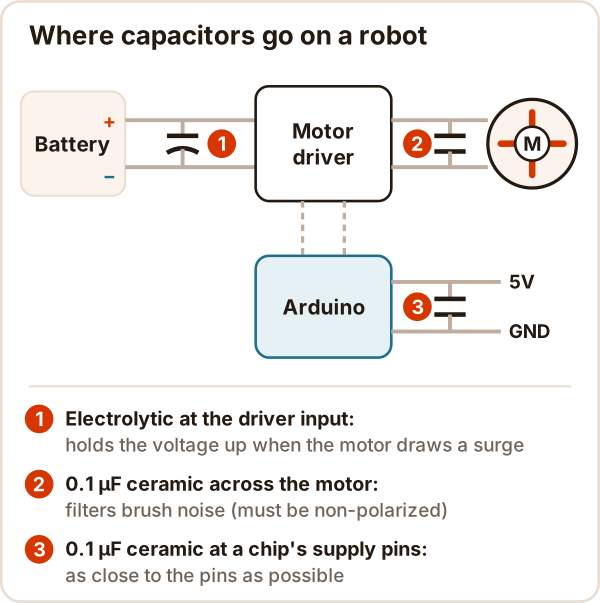
- Motor noise: a DC motor's brushes make electrical noise that can reset your Arduino. Solder a 0.1 µF ceramic across the motor terminals; the motor runs both ways, so never use a polarized one (how DC motors work).
- Supply dips: a starting motor pulls a current surge and the voltage sags for a moment. An electrolytic at the driver input covers the gap (the value is in the driver's datasheet).
- Chip supply (decoupling): 100 nF on every chip's power pins, as close as possible.
- Button bounce: 10 kΩ with 100 nF is a τ = 1 ms filter that smooths short bounces.
How to test a capacitor with a multimeter
Use the capacitance setting, but discharge the capacitor and take it out of the circuit first (how to use a multimeter):
- Turn the power off, discharge it as shown below, and check for 0 V.
- Remove it from the circuit: other parts throw off the reading.
- Turn the dial to capacitance (the capacitor symbol or F).
- Touch the probes to the legs (red to + on an electrolytic) and wait a few seconds.
- Compare with the label; a difference within the tolerance is normal (often ±20% for electrolytics).
"OL" means the value is above the range or the capacitor is bad. A bulging or leaking electrolytic doesn't need testing: replace it.
No capacitance setting? Measure τ with an Arduino
Wiring: D8 through 10 kΩ to a node; D9 through 1 kΩ to the same node. The node goes to A0 and to the + leg of a 100 µF capacitor; the − leg goes to GND (what is Arduino).
// RC charge curve: a 100 µF cap charges through 10 kΩ; A0 measures its voltage.
const int CHARGE_PIN = 8;
const int DISCHARGE_PIN = 9;
const int SENSE_PIN = A0;
const float R_OHM = 10000.0;           // charging resistor

void setup() {
  Serial.begin(9600);
}

void loop() {
  // 1) Discharge: D8 floats, D9 goes LOW (to GND through 1 kΩ)
  pinMode(CHARGE_PIN, INPUT);
  pinMode(DISCHARGE_PIN, OUTPUT);
  digitalWrite(DISCHARGE_PIN, LOW);
  while (analogRead(SENSE_PIN) > 2) { }
  delay(300);
  pinMode(DISCHARGE_PIN, INPUT);

  // 2) Charge and print the voltage every 50 ms
  pinMode(CHARGE_PIN, OUTPUT);
  digitalWrite(CHARGE_PIN, HIGH);
  unsigned long start = millis();
  unsigned long tau = 0;
  while (millis() - start < 5000) {    // 5 s = 5τ (10 kΩ × 100 µF = 1 s)
    int raw = analogRead(SENSE_PIN);   // 0..1023, 5 V = 1023
    if (tau == 0 && raw >= 647) {      // 647 = 63.2% of 1023
      tau = millis() - start;
    }
    Serial.println(raw * 5.0 / 1023.0);
    delay(50);
  }
  Serial.print("tau (ms): ");
  Serial.println(tau);
  Serial.print("C (uF): ");
  Serial.println(tau * 1000.0 / R_OHM);  // C = tau / R
  delay(3000);
}
Open the Serial Monitor (9600) to see the voltage rise, then τ and C = τ / R. Thanks to tolerance, anything from 0.8 to 1.2 s is normal; the sketch measures in 50 ms steps.
How to discharge a capacitor safely
Safety: do not open camera flashes, microwave ovens, air conditioners or TVs. Their capacitors can hold a potentially lethal charge even after the device is unplugged. A faulty AC unit capacitor is a job for a qualified technician.
Only for small, low-voltage capacitors like the ones in a robot kit:
- Turn the power off.
- Clip a resistor of about 1 kΩ across the legs with alligator leads; for 1000 µF, wait 5 seconds (5τ).
- Check for 0 V with a multimeter. An electrolytic that sits for a while can build up a little charge again, so discharge it again before use.
Don't short it with a screwdriver: it sparks and damages the leads and the capacitor.
Why do capacitors explode?
- Reverse polarity: the manufacturer warns that reverse voltage can short or damage an electrolytic and open its pressure-relief vent early. It heats up, bulges and can burst.
- Over-voltage: going past the printed voltage destroys it. Leave margin: on a 12 V circuit, pick a 25 V part, for example.
The first time you power a new circuit, don't lean over the electrolytics, and wear safety glasses.
Common mistakes
| Symptom | Cause | Fix |
|---|---|---|
| Arduino resets when the motor starts | Motor noise, supply dip | 0.1 µF across the motor, electrolytic at the driver input; power the motor from its own battery |
| Electrolytic gets hot or bulges | Reversed, or voltage rating too low | Power off; fit a new one the right way round with a higher rating |
| The capacitor across my motor blew | It was polarized; reversing the motor reversed its voltage | Use a non-polarized ceramic |
| Multimeter reading differs from the label | Measured in circuit, or tolerance | Remove it, discharge it, measure again |
| Arduino sketch prints tau 0 | It never reached 63% within 5 s | Check the wiring, the capacitor's direction and its value |
| I read 104 as 104 µF | The code is in pF | 104 = 100 nF = 0.1 µF |
Sources
Accessed: 17 October 2026
- OpenStax University Physics 2: 8.1 Capacitors and Capacitance (C = Q/V, parallel-plate formula), 8.2 Series and Parallel, 8.3 Energy Stored (½CV²), 10.5 RC Circuits (τ = RC, 63.2% and 36.8%).
- SparkFun, Capacitors: symbols, units, electrolytic polarity, series/parallel, 0.1 µF decoupling.
- Pololu, Dealing with Motor Noise: 0.1 µF ceramic across motor terminals, no polarized capacitors, resets.
- Nippon Chemi-Con, Precautions and Guidelines, Aluminum Electrolytic Capacitors: reverse voltage, rated voltage, pressure-relief vent, discharging through about 1 kΩ.
- Vishay, MLCC Marking: the third digit is the multiplier.
- Fluke, How to Measure Capacitance: discharge first, remove from circuit, OL.
- Arduino Docs, Capacitance Meter: finding capacitance by timing the rise to 63.2%.
- Technical Safety BC, Microwave oven incident report II-1399412-2022: a microwave capacitor can deliver a potentially lethal shock after unplugging.