What we'll do
- Look inside a relay and see why it clicks.
- Learn the difference between the NO, NC and COM terminals.
- Wire a relay to an Arduino Uno the right way and switch it from code.
- Try a self-latching circuit with START and STOP buttons.
- Check whether a relay is good with a multimeter.
Why it's useful: an Arduino pin can only supply a small current. A relay uses that small signal to switch a 12 V pump, lamp or LED strip, while keeping that circuit separate from the Arduino.
What is a relay used for?
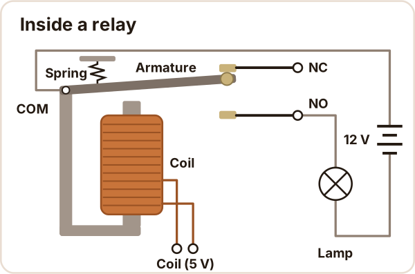
A relay is a switch you control with electricity: a small coil current opens or closes a contact in a separate circuit. The two circuits are not electrically connected; a magnet and a spring do the work in between.
- Control side: the coil. Example: the 5 V SRD-05VDC-SL-C has a 70 Ω coil that draws 71.4 mA.
- Load side: the contacts (COM, NO, NC). The lamp, pump or fan current flows here.
- In robotics: 12 V pumps, water valves, lamps, LED strips, horns. All low voltage.
Safety: every example here runs at 12 V or less. Relay modules often say "250VAC" on them, but wiring mains (120 V or 230 V) is a job for a licensed electrician, with a closed enclosure, a fuse and certified parts. Students and teams should never wire mains.
How does a relay work?
When current flows through the coil, the iron core becomes a magnet and pulls the armature toward it. When the current stops, the spring pulls the armature back.
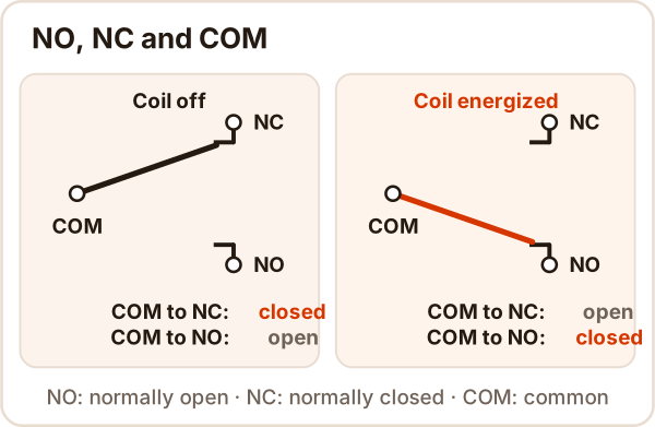
- Coil off: the spring holds the armature up, so COM touches NC.
- Coil energized: the magnetic field pulls the armature down and COM moves to NO. That is the click you hear.
- Coil off again: the spring pulls the armature back and COM returns to NC.
According to the datasheet, this relay pulls in within 10 ms at most, and it is guaranteed to pull in at no more than 75% of its rated voltage (3.75 V for a 5 V coil).
What do NO, NC and COM mean?
| Terminal | Stands for | Coil off | Coil energized |
|---|---|---|---|
| COM | Common | Connected to NC | Connected to NO |
| NO | Normally open | Open | Connected to COM |
| NC | Normally closed | Connected to COM | Open |
Rule of thumb: if the load should turn on when the relay clicks, wire it between COM and NO. If it should turn off when the relay clicks, use COM and NC.
Relay symbol
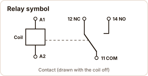
In a schematic the coil is a rectangle (A1, A2), and the contact is drawn in its coil-off position. The dashed line shows the mechanical link. Industrial relays often number the terminals 11 (COM), 12 (NC) and 14 (NO).
Try it yourself
Set the pin HIGH first, then move the lamp to NC. Next, pick "Transistor, no diode", set the pin LOW, and finally open the Self-latching circuit tab.
This is an interactive demo where you set the pin HIGH or LOW, watch the relay pull in, see when a lamp on NO or NC turns on, and try a self-latching circuit with START and STOP buttons. It needs JavaScript; if it did not load, the drawings above show the same states.
How do you connect a relay to an Arduino?
You don't connect a relay coil straight to an Arduino pin. A 5 V coil needs 71.4 mA, while the ATmega328P on an Arduino Uno has an absolute maximum of 40 mA per pin. There are two good ways:
| Option | What you need | When |
|---|---|---|
| Relay module | All on one board: relay, driver circuit, LED, usually an optocoupler | Quick builds, classes, prototypes |
| Bare relay | NPN transistor, base resistor, diode across the coil | When you design your own board |
Bare relay: transistor and diode
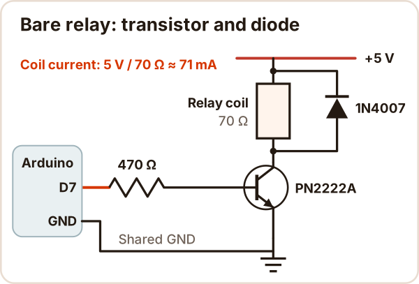
The transistor carries the coil current; the pin only supplies about 9 mA of base current. The diode is not optional: when the coil turns off it produces a reverse voltage spike, and without the diode that spike can destroy the transistor. The math and the pin order are in the transistor post.
Relay module pins
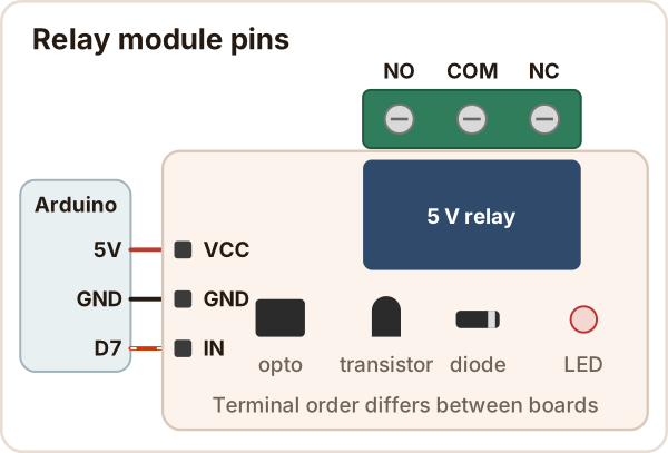
- VCC, GND, IN: the Arduino's 5V, GND and a digital pin.
- NO, COM, NC: the screw terminal, where the load goes. The order differs between boards, so read the label.
- JD-VCC jumper (on some modules): with the jumper on, the coil runs from the Arduino's 5V. Take it off, feed JD-VCC from a separate 5 V supply, and the optocoupler keeps the two sides apart.
- LOW or HIGH? Many modules switch on when IN goes LOW. Pick yours with one line in the code.
Arduino code: toggle the relay every 2 seconds
// Relay module: IN on D7, VCC to 5V, GND to GND.
// If your module switches on with HIGH, change ON to HIGH.
const int RELAY_PIN = 7;
const int ON = LOW;                           // many modules switch on with LOW
const int OFF = (ON == LOW) ? HIGH : LOW;

void setup() {
  digitalWrite(RELAY_PIN, OFF);  // write "off" first so the relay does not click at startup
  pinMode(RELAY_PIN, OUTPUT);
}

void loop() {
  digitalWrite(RELAY_PIN, ON);   // relay pulls in: COM moves to NO
  delay(2000);
  digitalWrite(RELAY_PIN, OFF);  // relay releases: COM goes back to NC
  delay(2000);
}
A relay is not for fast switching: the datasheet allows at most 30 operations per minute under load, and you cannot use PWM through it to set speed or brightness. For motor speed, see the drivers in the DC motor post.
What is a self-latching relay circuit?
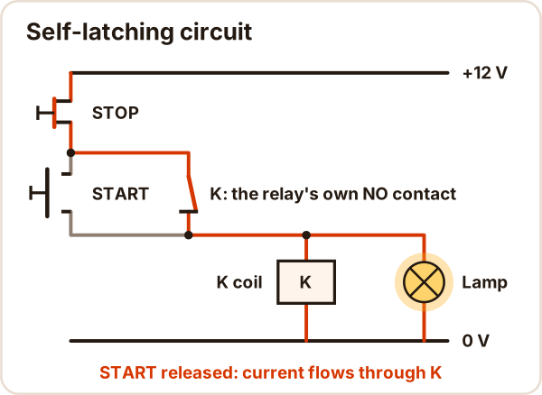
A self-latching (or holding) circuit keeps a relay on after one press of START, through the relay's own NO contact.
- Press START: current flows through START to the coil, the relay pulls in and its K contact closes.
- Release START: current now comes through K, so the relay stays on.
- Press STOP: the line is broken, the coil drops out and K opens. It stays off after you release STOP.
After a power cut the machine does not restart on its own; someone has to press START again. That is why machines use this circuit so often. In the second tab of the demo, untick "Latching contact" to see the difference.
How do you test a relay?
With a multimeter, on a relay removed from the circuit:
- Coil resistance: ohms mode across A1 and A2. For the SRD-05VDC-SL-C expect 70 Ω ±10% (63 to 77 Ω). OL on the display means the coil is open.
- Contacts at rest: in continuity (beep) mode, COM to NC beeps, COM to NO does not.
- Contacts pulled in: put 5 V on the coil (for example the Arduino's 5V and GND pins). You should hear a click, and now COM to NO beeps while COM to NC does not.
What are SSRs and reed relays?
| Type | How it switches | Pros | Watch out for |
|---|---|---|---|
| Mechanical relay | Coil, armature, contacts | Cheap, no leakage when off, AC or DC loads | Clicks, contacts wear |
| SSR (solid-state relay) | Optocoupler plus a semiconductor (triac for AC, MOSFET or transistor for DC) | No moving parts, silent, long life | Gets warm, small leakage current when off, AC and DC types differ |
| Reed relay | Two thin metal reeds in a glass tube, with a coil around it | Very small and fast (about 0.5 ms to a few ms) | Small currents only |
Common mistakes
| Symptom | Cause | Fix |
|---|---|---|
| Relay won't pull in, or pulls in unreliably | Coil wired straight to the pin (needs 71 mA, pin limit 40 mA) | Use a module or a transistor |
| Relay works backwards | Module switches on with LOW | Change ON in the code |
| Relay clicks once at startup | pinMode comes first |
Write digitalWrite(OFF) first, then pinMode |
| Lamp is always on | Load wired to NC | Move it to COM and NO |
| Transistor died quickly | No diode across the coil | Add a 1N4007 across the coil, reversed |
| Relay clicks but the load does nothing | No power in the load circuit | The contact is only a switch; the load needs its own supply |
Sources
Accessed: 17 October 2026
- Songle, SRD series relay datasheet: 5 V coil 70 Ω and 71.4 mA, 12 V coil 400 Ω and 30 mA, pull-in voltage 75% max, operate time 10 ms max, 30 electrical operations per minute.
- Microchip, ATmega48A/88A/168A/328P datasheet: absolute maximum DC current per I/O pin 40 mA.
- SunFounder Arduino kit docs, 2 Channel Relay Module: LOW trigger, JD-VCC jumper, optocoupler isolation.
- Electronics Tutorials, Relay Switch Circuit: driving a relay with a transistor and the diode across the coil.
- Electronics Tutorials, Solid State Relay: SSR construction, optocoupler, AC and DC outputs.
- Broadcom, Solid State Relays application note (AV02-2321EN): off-state leakage and on-state voltage drop.
- Electronics Notes, What is a Reed Relay: glass envelope, low current, switching in about 0.5 ms to a few ms.