What we'll do
- See what a transistor is and how it works as a switch.
- Find the E, B and C pins (two common parts have them in opposite order).
- Calculate the base resistor and try it in a simulator.
- Drive a motor from an Arduino safely, with a diode.
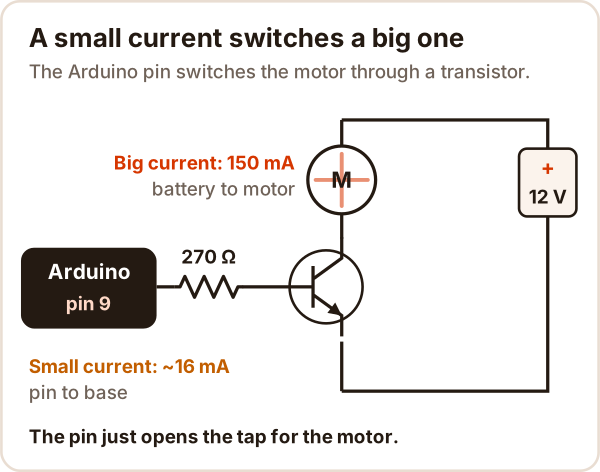
Why it's useful: an Arduino pin can only supply a few tens of milliamps, while a motor, relay or LED strip wants far more. A transistor lets that small pin signal switch the big current.
What is a transistor and what does it do?
A transistor is a three-legged semiconductor part that uses a small current to switch, or amplify, a much bigger one.
- Switch: the main job in robotics. Pin HIGH, the motor runs; pin LOW, it stops.
- Amplifier: it makes a weak signal, like a microphone's, bigger.
- Digital logic: processors contain billions of them, each working as a tiny switch.
In short: a small current into the base lets a big current flow from collector to emitter.
How does a transistor work?
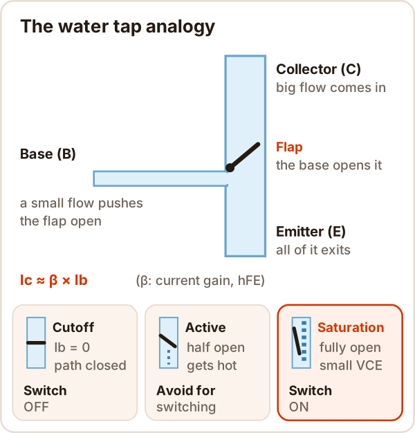
In an NPN transistor, a small current (Ib) flowing from base to emitter opens the path between collector and emitter. The big current is roughly Ic ≈ β × Ib, where β (hFE) is the current gain.
| State | What happens | As a switch |
|---|---|---|
| Cutoff | Ib = 0, path closed | Off |
| Active | Path half open, the transistor heats up | Avoid |
| Saturation | Path fully open, VCE around 0.3 V | On |
As a switch you always want cutoff or saturation, nothing in between.
Transistor symbols and types (NPN, PNP, MOSFET)
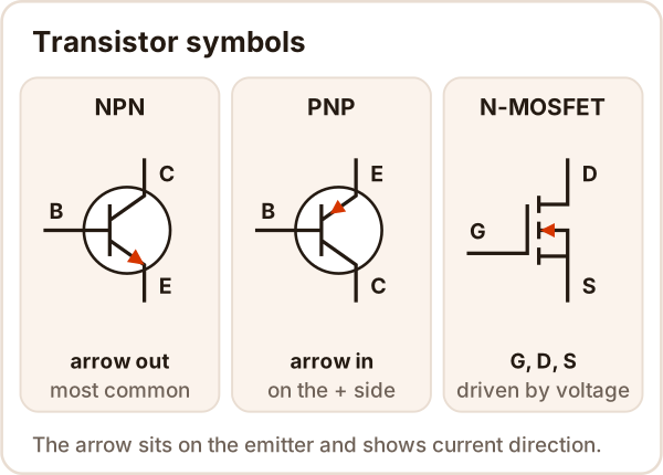
- NPN: goes between the load and ground, turns on when the pin is HIGH. The easiest with an Arduino.
- PNP: goes on the positive side of the load, turns on when the base is pulled LOW. Needs an extra stage if the supply is above 5 V.
- MOSFET: driven by gate voltage instead of current; better for loads of an amp or more.
How do you find the E, B and C pins?
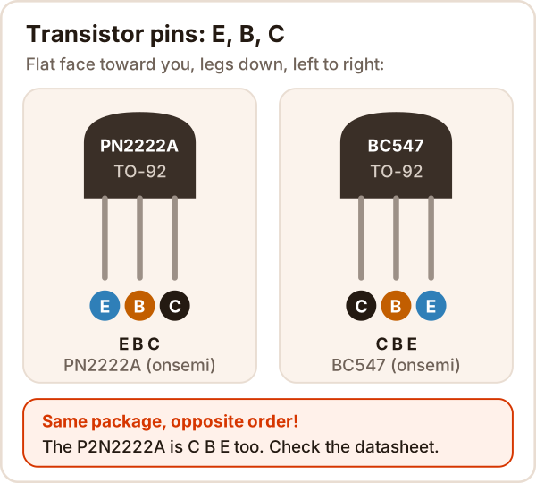
The pin order depends on the part and the maker. Flat face toward you, left to right:
- PN2222A: E, B, C
- BC547: C, B, E
- P2N2222A: C, B, E (almost the same name, opposite order!)
If you are not sure, check the datasheet or test it with a multimeter (below).
How do you calculate the base resistor?
The base resistor (Rb) protects the pin and turns the transistor fully on. The rule:
Ib = Ic / 10                 (so it stays fully on)
Rb = (5 V - 0.7 V) / Ib
Example: a motor drawing 150 mA. Ib = 15 mA, Rb = 4.3 / 0.015 = 287 Ω. The next standard value down: 270 Ω.
- Why Ic/10? β varies from part to part and with temperature. The PN2222A datasheet specifies its saturation voltage at exactly this ratio: 15 mA of base current at 150 mA.
- Pin limit: the ATmega328P (Arduino Uno) has an absolute maximum of 40 mA per pin, and the datasheet tests at 20 mA. If Ib would go above 20 mA, use a MOSFET instead of a BJT.
Simulator: switching an LED, a motor and a relay
Try this: pick Motor, set the pin HIGH and drag the base resistor up to 10 kΩ. Watch the motor slow down and the heat in the transistor rise. Then untick the diode and set the pin LOW.
This is an NPN transistor simulator and base resistor calculator; it needs JavaScript. If it does not load, the formula above does the same math.
Driving a motor with a transistor and an Arduino
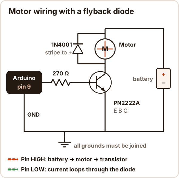
Parts: Arduino Uno, PN2222A, 270 Ω, 1N4001 diode, small DC motor (150 mA running current at most), a separate battery for the motor.
- Emitter to GND, base through 270 Ω to pin 9; motor between battery + and the collector.
- Diode across the motor, stripe toward +.
- Battery negative to Arduino GND.
// Motor speed with a transistor (Arduino Uno)
// Pin 9 -> 270 Ω -> PN2222A base. Motor between +V and the collector.
// 1N4001 diode across the motor: striped end to +V. Emitter and Arduino GND shared.
const int MOTOR_PIN = 9;  // PWM pin (marked ~)

void setup() {
  pinMode(MOTOR_PIN, OUTPUT);
}

void loop() {
  // Speed up slowly: 0 (stopped) ... 255 (full speed)
  for (int speed = 0; speed <= 255; speed += 5) {
    analogWrite(MOTOR_PIN, speed);
    delay(40);
  }
  delay(1000);           // 1 second at full speed
  // Slow down slowly
  for (int speed = 255; speed >= 0; speed -= 5) {
    analogWrite(MOTOR_PIN, speed);
    delay(40);
  }
  delay(1000);           // stop for 1 second
}
On the Uno, analogWrite switches the pin about 490 times a second (PWM); the share of on-time sets the speed. More on motors: How DC motors work
Why the diode? A motor is a coil. When the transistor switches off, the coil current cannot stop instantly, so it produces a high voltage spike. The diode gives that current a loop around the motor to die out in, protecting the transistor. The same goes for relay coils: What is a relay?
When a motor starts or stalls, it draws much more current than while running. Pick the transistor for that current.
Transistor vs MOSFET: what's the difference?
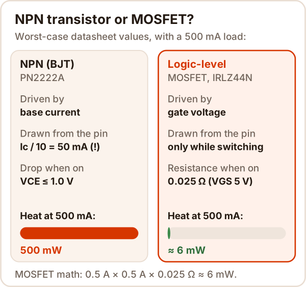
| NPN (PN2222A) | Logic-level MOSFET (IRLZ44N) | |
|---|---|---|
| Driven by | Base current (Ic/10) | Gate voltage |
| When on | VCE 0.3-1 V | RDS(on) 0.025 Ω (VGS 5 V) |
| Load from an Arduino pin | Up to about 200 mA (Ib at most 20 mA) | Amps |
| Use it for | LED, small motor, relay | Big motor, LED strip |
A logic-level MOSFET's datasheet gives RDS(on) at a gate voltage of 5 V or less.
How do you test a transistor with a multimeter?
Set the meter to diode test. For an NPN:
| Red probe | Black probe | Good transistor |
|---|---|---|
| B | E | About 0.6-0.7 V |
| B | C | A slightly lower value |
| E or C | B | OL (no conduction) |
| C ↔ E | both ways | OL |
The pair that reads slightly higher is B-E, which also tells you which leg is which. If any pair reads close to 0 both ways, the transistor is shorted. How to measure: How to use a multimeter
Common mistakes
| Symptom | Cause | Fix |
|---|---|---|
| Motor does not turn at all | Grounds not joined, or legs swapped | Connect battery negative to Arduino GND, check the pin order |
| Transistor gets very hot | Not fully on (Rb too big) or too much current | Use the Ic/10 rule for Rb, or a MOSFET |
| Arduino keeps resetting | Motor powered from the Arduino 5 V, no diode | Separate motor battery, add the diode |
| Transistor died after a few tries | No diode, voltage spike at switch-off | Fit a 1N4001 across the motor, reverse biased |
| MOSFET module will not fully turn on at 5 V | Not logic-level (e.g. IRF520: RDS(on) given only at 10 V) | Pick a logic-level MOSFET |
Sources
Accessed: 17 October 2026
- onsemi (Fairchild), PN2222A datasheet: TO-92 E-B-C, switching up to 500 mA, 625 mW, VCE(sat) 0.3 V (150 mA / 15 mA) and 1.0 V (500 mA / 50 mA), hFE.
- onsemi, BC546/BC547/BC548 datasheet: pin 1 collector, 2 base, 3 emitter; IC 100 mA; VCE(sat).
- onsemi, P2N2222A datasheet: pin 1 collector, 2 base, 3 emitter.
- Microchip, ATmega328P datasheet: 40 mA absolute maximum per pin, 20 mA test condition.
- Arduino Docs, analogWrite(): Uno PWM pins and 490 Hz.
- Infineon, IRLZ44N datasheet: RDS(on) 0.025 Ω (VGS 5 V), VGS(th) 1-2 V.
- Vishay, IRF520 datasheet: VGS(th) 2-4 V, RDS(on) only at VGS 10 V.
- Vishay, 1N4001-1N4007 datasheet: 1 A diode.
- T. Kuphaldt, Lessons in Electric Circuits, Vol. III: Diodes, inductive kickback and the commutating diode and Meter check of a transistor.