What we'll do
- Watch the coils inside a stepper motor switch on in order.
- Learn the difference between full steps, half steps and microsteps.
- Wire a 28BYJ-48 with a ULN2003, and a bigger motor with an A4988, to an Arduino.
- Use the calculator to find steps per revolution and the pulse rate you need.
Why it's useful: a stepper is the easiest way to say "turn exactly 90 degrees" or "move 5 mm" without any sensor. That's why 3D printers and CNC machines use them.
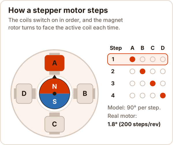
What is a stepper motor used for?
A stepper motor turns by a fixed angle (one step) for every electrical pulse. Count the pulses and you know where the shaft is, with no extra sensor.
Where you'll find them: 3D printer and CNC axes, laser cutters, camera sliders, turntables, scanners.
How does a stepper motor work?
The rotor is a magnet surrounded by coils. A coil with current through it becomes a magnet and pulls the rotor toward it. Switch the coils on and off in order and the rotor turns step by step.
In a real motor the rotor and stator have fine teeth, so the steps are tiny: on common motors one step is 1.8°, or 200 steps per revolution.
- How far it turns: depends on the number of pulses.
- How fast it turns: depends on how often the pulses come.
Full step, half step, microstepping
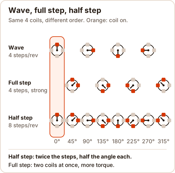
- Wave drive: one coil on per step. Low current, low torque.
- Full step: two neighboring coils together. About 1.4 times the torque of wave drive, at twice the power.
- Half step: alternate one coil and two. Twice as many steps (400 instead of 200).
- Microstepping: drivers like the A4988 set the coil currents in small increments to split each step up to 16 ways (3200 instead of 200). Motion gets smoother.
Try it yourself
Pick a drive mode and press 1 step or Play: watch which coil lights up and where the rotor turns. Then work out your own mechanism below.
This is a simulator where you fire the coils in order and watch the rotor step, plus a calculator for steps per revolution, pulse frequency and steps per mm; it needs JavaScript. If it didn't load, the pictures above show the same sequence.
Try this: in half step, press eight times and the model rotor makes one full turn. Then pick a 1.8° motor, 1/16 and a 20-tooth GT2 pulley in the calculator: one step is 0.0125 mm, so 1 mm takes 80 pulses.
Unipolar vs bipolar stepper motors
| Unipolar | Bipolar | |
|---|---|---|
| Wires | 5 or 6 (coils have a center tap) | 4 |
| Driver | Simple: a transistor array like the ULN2003 | One H-bridge per coil: A4988, L298N |
| Example | 28BYJ-48 (5 wires) | 1.8° motors (the NEMA 17 size in 3D printers) |
A bipolar motor needs the current in each coil to reverse, so every coil needs its own H-bridge, like the one in the DC motor guide.
What is a stepper driver? ULN2003 and A4988
The coils draw more current than an Arduino pin can supply; the driver switches that current on the Arduino's command.
- ULN2003: seven transistor pairs, up to 500 mA per output. It switches the four coils of a 28BYJ-48.
- A4988: a bipolar driver; 8-35 V, about 1 A per phase without cooling, 1/16 microstepping. The Arduino only sends STEP (one pulse, one step) and DIR (direction).
How to wire a 28BYJ-48 to a ULN2003
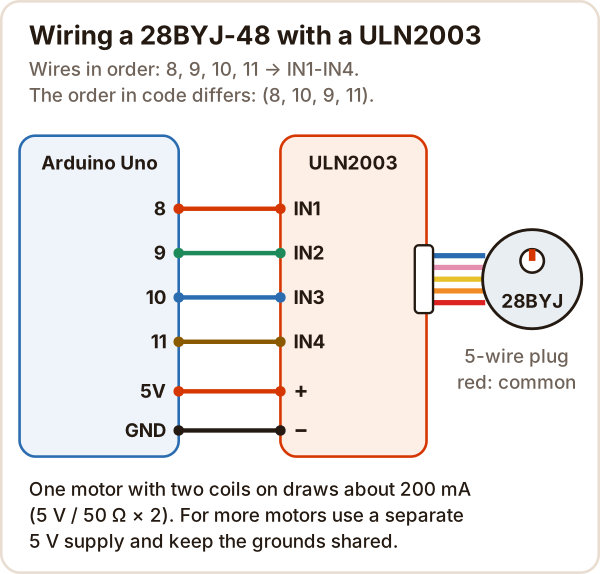
// 28BYJ-48 + ULN2003: one turn forward, one back, with the Stepper library
#include <Stepper.h>

const int STEPS_PER_REV = 2048;  // full steps per turn (catalog value)
// Order matters: IN1, IN3, IN2, IN4 -> pins 8, 10, 9, 11
Stepper motor(STEPS_PER_REV, 8, 10, 9, 11);

void setup() {
  motor.setSpeed(10);            // rpm; 10-15 suits the 28BYJ-48
}

void loop() {
  motor.step(STEPS_PER_REV);     // one turn forward (waits until done)
  delay(1000);
  motor.step(-STEPS_PER_REV);    // one turn back
  delay(1000);
}
- Why 8, 10, 9, 11? The library drives its pins in its own order; written this way, the coils fire in pairs in the order A, B, C, D. Write 8, 9, 10, 11 and the motor just buzzes.
- 2048 or 2038? The datasheet's 1/64 ratio gives 2048 full steps per turn. People who counted the gear teeth found the real ratio is 63.68:1, about 2038 steps. In long-running projects like clocks the difference adds up: run 10 turns and measure.
- Speed: the datasheet only says the no-load start frequency is "greater than 600 Hz". Start at 10-15 rpm (15 rpm = 512 steps/s).
How to wire a stepper to an A4988
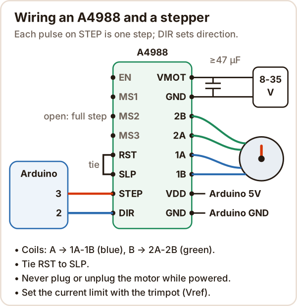
// A4988 + 1.8° bipolar stepper: turns with STEP/DIR
const int STEP_PIN = 3;
const int DIR_PIN = 2;
const int STEPS_PER_REV = 200;  // MS1-MS3 unconnected: full step

void setup() {
  pinMode(STEP_PIN, OUTPUT);
  pinMode(DIR_PIN, OUTPUT);
}

// send `steps` pulses; gapUs: time from one pulse to the next
void move(int steps, bool forward, unsigned int gapUs) {
  digitalWrite(DIR_PIN, forward ? HIGH : LOW);
  for (int i = 0; i < steps; i++) {
    digitalWrite(STEP_PIN, HIGH);
    delayMicroseconds(gapUs / 2);  // datasheet: at least 1 µs
    digitalWrite(STEP_PIN, LOW);
    delayMicroseconds(gapUs / 2);
  }
}

void loop() {
  move(STEPS_PER_REV, true, 5000);   // 200 Hz = 60 rpm
  delay(1000);
  move(STEPS_PER_REV, false, 5000);  // back
  delay(1000);
}
- Current limit: set with the trimpot on the board. On the Pololu board the formula is Vref = 8 × I × Rcs; with Rcs = 0.068 Ω, 1 A needs Vref ≈ 0.54 V. Other boards may use a different resistor, so check yours.
- Capacitor: at least 47 µF across VMOT and GND, close to the board. Voltage spikes can damage the driver.
- Microstepping: MS1, MS2, MS3 open means full step; all three HIGH means 1/16, and
STEPS_PER_REVbecomes 3200. - Never plug or unplug the motor while powered: it can destroy the driver.
What voltage does a stepper motor need?
- 28BYJ-48: the version in the datasheet is 5 V. Check the voltage printed on your motor.
- Bipolar motors: the rated voltage on the label is often low, but with a current-limiting driver like the A4988 you run them from a higher supply (8-35 V), which lets them step faster. Keep the current limit at or below the motor's rated current.
A stepper draws current even when standing still, to hold its position, so it gets warm while idle too.
How to identify stepper motor wires
Set your multimeter to resistance (ohms):
- 4 wires (bipolar): if you read a resistance between two wires, they're the same coil; if not, they're different coils. You'll find two pairs: one goes to 1A-1B, the other to 2A-2B.
- 5 wires (28BYJ-48): red is the common; you'll read the same resistance from red to each of the other wires.
- Turns the wrong way? Swap the two ends of one coil, or flip DIR in code.
Stepper vs servo motor
| DC motor | Servo motor | Stepper motor | |
|---|---|---|---|
| Motion | Spins continuously | Goes to an angle, most 0-180° | Step by step, can also spin |
| How it knows position | It doesn't, needs an encoder | Measures it internally | Counts pulses, no measurement |
| Driving it | H-bridge + PWM | One signal wire | Driver + pulse train |
| Weak spot | Needs a sensor and PID for position | Limited angle | Skips steps under overload and never notices |
More detail: what is a servo motor?
Common mistakes
| Symptom | Cause | Fix |
|---|---|---|
| 28BYJ-48 buzzes but won't turn | Pins written as 8, 9, 10, 11 | Stepper motor(2048, 8, 10, 9, 11) |
| Bipolar motor jitters | Coil pairs mixed up | Find the pairs with a multimeter |
| A4988 does nothing | RST left floating | Tie RST to SLP |
| Position drifts over time | Too fast, too much load, or current limit too low | Slow down, accelerate gently, check Vref |
| Motor and driver run very hot | Current limit too high | Set Vref for the motor's rated current |
| 28BYJ-48 is a bit off after a full turn | Real gear ratio is 63.68:1 | Use your measured value instead of 2048 |
Sources
Accessed: 17 October 2026
- Douglas W. Jones (University of Iowa), Control of Stepping Motors: Stepping Motor Types: unipolar and bipolar, wave drive, full and half step, about 1.4 times the torque.
- Kiatronics, 28BYJ-48 5V Stepper Motor datasheet (CERN course copy): 5 V, 4 phases, 1/64, 5.625°/64, no-load start frequency > 600 Hz.
- Arduino Forum, Geared Stepper Motor: gear tooth count and the 63.68395:1 ratio.
- Arduino, Stepper library and source code: 4-wire step sequence,
setSpeed()andstep(). - Pololu, A4988 Stepper Motor Driver Carrier: 8-35 V, about 1 A per phase, MS table, RST-SLP, 47 µF, current limit formula.
- Allegro, A4988 datasheet: STEP pulse at least 1 µs.
- Texas Instruments, ULN2003A datasheet: Darlington array, 500 mA per output.
- Prusa Research, RepRap Calculator: 2 mm tooth pitch for GT2 belts.