0.8 Introduction to electronic parts
Being written
This page is being written and will be updated again on 30 September 2026. For now comments are collected on the Turkish version of this page (language menu): if you find something missing or wrong, you can write it there. The feedback we receive decides what changes in this round.
What you learn in this lesson
How motors and servos are controlled, where the robot gets its energy from, and what information we can measure with sensors.
When you read on a computer, you can click any heading in the section list on the right to jump straight to that section.
Motors and servos
In the last lesson we looked at the parts that carry motion. The parts that start motion are motors and servos. Both run on electricity and turn a shaft. The difference between them decides which one you pick for which kind of motion.
Motors
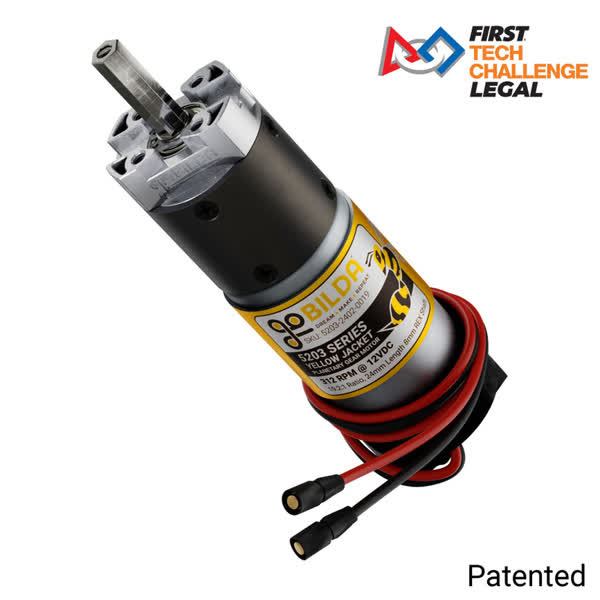
When you give power to a DC motor, the shaft at its end turns. The body of the motor is fixed to the robot's structure and stays in place, and the turning shaft carries the motion to wheels, gears or a belt. Turning wheels, spinning a mechanism nonstop or moving a heavy part is the motor's job.
The motors used in FTC differ from each other in a few ways. Some are big and strong and are the usual choice for the wheels that drive the chassis. Some are smaller and suit mechanisms that have to fit into tight spaces. REV HD Hex, REV Core Hex and goBILDA Yellow Jacket are motors you will often see on these robots.
The same motor family is also sold with different gearbox ratios. In 0.7 Introduction to mechanical parts we saw that a gearbox changes the speed and the turning force at the motor's output. That is why you can find both a fast-spinning option and an option that turns heavier loads in the same product. Whether the motor has an encoder inside that takes measurements is another difference between products. We will look at that later in this lesson.
Servos
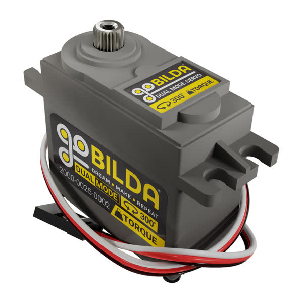
When you give power to a motor, the shaft turns, but the motor itself does not know where to stop. On a robot, though, there are parts that you want to go to a certain place and stay there. Keeping a claw open or closed is that kind of job, and a servo is used for it.
Servos come in two types. A position-controlled servo works within a certain angle range. You tell it the angle you want it to go to, the servo goes to that angle and stays there until a new command comes. Opening and closing a claw, or moving a part between two positions, is done with this type. The angle range they can turn through changes from product to product, so when you choose one, check the range on the product page.
A continuous rotation servo does not go to an angle. You give it a direction and a speed, and it keeps turning that way until the command changes. For jobs like turning a small spool or spinning a conveyor, it acts like a small motor. You cannot tell this type of servo an angle, because the servo does not keep track of its own position.
Some servos support both modes, and you can set which mode they work in. goBILDA's 2000 Series dual mode servos work like this.
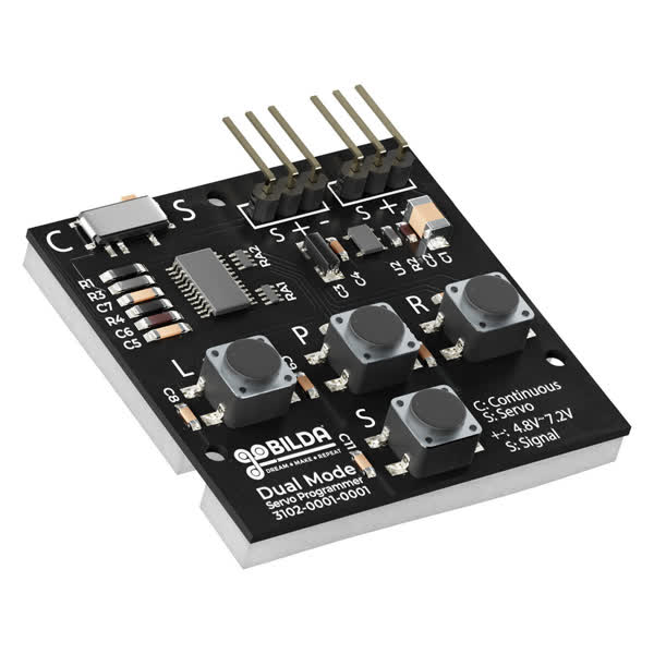
To try out a servo's motion without writing a robot program, there are servo test boards. You give the servo connected to the board a command from the board itself and watch the motion right there.
Both the motor and the servo run on electrical energy. Let's look at where this energy comes from on the robot.
Battery and main power switch
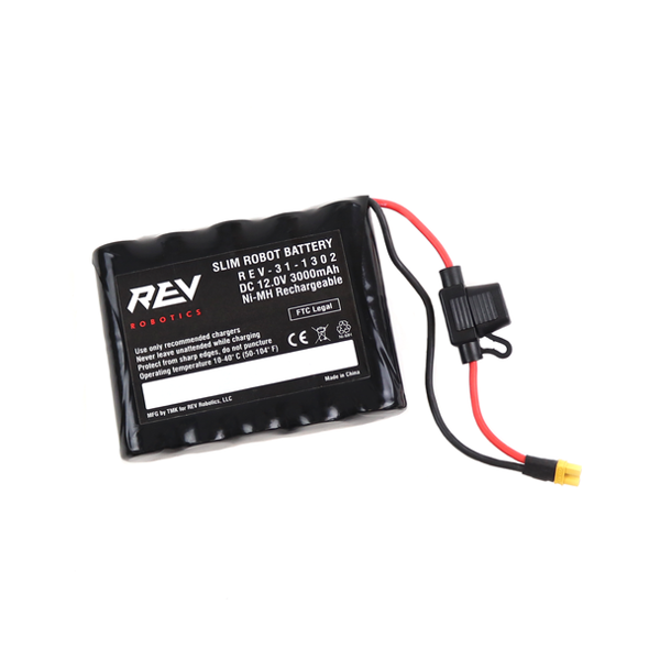
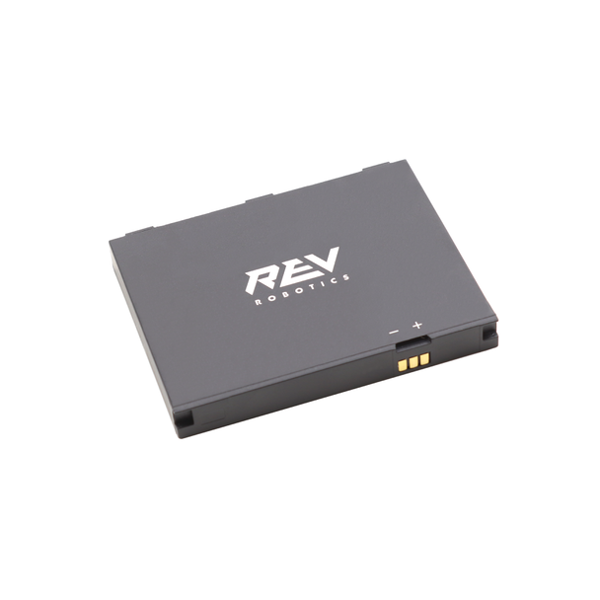
The energy for the motors, servos and electronic boards on the robot comes from the robot battery. The battery is connected to the robot, and when it runs down it is recharged with a charger that suits it.
The NiMH and Li-ion in battery names tell you which chemistry stores the energy inside the battery. NiMH means nickel metal hydride, and Li-ion means lithium-ion. In the current REV control setup, the robot's main battery is a 12 V NiMH pack, while the Driver Hub on the driver's side has its own Li-ion battery. These are not two free alternatives you can swap on the robot; they are the approved batteries of different devices. The charger also has to match the chemistry and model of the battery you use.
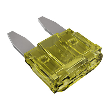
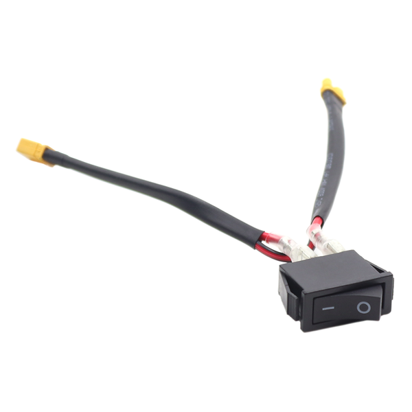
There is a fuse on the line coming out of the battery. When the current through the circuit goes above a safe limit, the fuse cuts the line and protects the electronics. REV's 12 V battery uses a 20 A blade fuse, similar to the ones in cars, and this fuse can be replaced. A blown fuse is replaced with a new one of the same rating. The rules do not allow you to bypass the fuse or replace it with a higher-rated one.
The robot has a main power switch that turns the power coming from the battery on and off. When the switch is off, the main power from the battery is cut. This is where you turn the robot on and off, both on the field and in the workshop. The device in the driver's hands has its own power; it does not run on the robot's battery.
Because the robot battery is also used in the workshop, it gets charged and drained many times over the season and wears out over time. Driver practice makes up part of these charge cycles. For these sessions, where nobody is tuning the robot and drivers just drive for hours, you can keep a separate test battery.
Lithium-ion packs can be used as a test battery. This battery belongs in the workshop, because the Competition Manual only allows one of the listed 12 V NiMH batteries on the robot during competition. The test battery does not go to tournaments.
A lithium-ion battery needs its own charger. The NiMH charger that came in your robot battery's box is not suitable for this, so do not plug the test battery into it. Stay with the battery while it charges; do not leave it charging and walk away.
Giving energy to a DC motor makes it turn, but it does not stop it where and when you want. You need something that decides when the motor turns, in which direction and for how long. On a robot, the program you write makes this decision, and this is where the board that runs the program comes in.
Control Hub and Expansion Hub
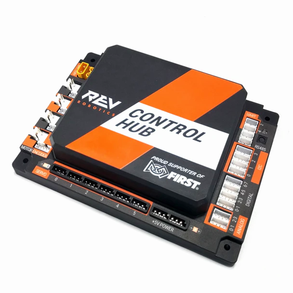
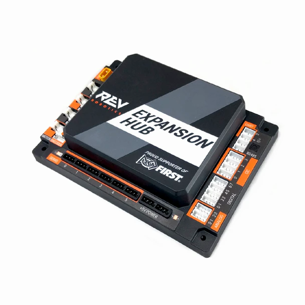
The Control Hub is the board that runs the robot's program. You could call it the robot's brain. The concrete job it does is to run the program you write and, following that program's commands, tell the motors and servos connected to it what to do. The motors and servos connect to this board with their cables.
The Expansion Hub is a second board you add to the robot when you need extra motor, servo and sensor connections. It communicates with the Control Hub and works under it. The program still runs on the Control Hub.
Each hub has four motor ports and six servo ports. The number of ports is not the limit on how many motors and servos you can use on the robot. Rule V0 R503 in the 2026-27 BIOBUZZ season Competition Manual sets a limit of eight motors and eight servos in total per robot. So the twelve servo ports on two hubs do not mean you are allowed to use twelve servos. You can check this number in the Competition Manual for your own season.
We will look at how we write what the program does, and which tools we use, in the 0.9 Software lesson. Placing the boards on the robot and running their cables is the topic of the 1.2 Electronics layout and cables lesson.
Gamepad and Driver Hub
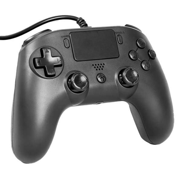
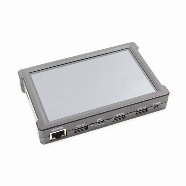
In the driver-controlled period of the match, a person drives the robot. The driver holds a gamepad and gives commands with its sticks and buttons. The gamepad does not connect to the robot; it connects to the device on the driver's side. The Driver Hub is one of the driver devices you can use for this. The app that runs on the device is called Driver Station. One is the hardware, the other is the software that runs on that hardware.
When the driver pushes a stick, the command goes to the robot over a wireless connection. The program running on the robot receives the command and tells the motors what to do. The energy that turns the motor still comes from the robot battery; the gamepad carries information, not energy.
The command from the gamepad tells the robot what it should do; it does not tell you what is actually happening. Neither the driver nor the program can learn from this command how far a mechanism has gone, how much the wheels have turned, or whether there is something in front of the robot. The parts that measure this information are called sensors, and in the rest of the lesson we will look at the ones that are common on FTC robots.
Limit switch
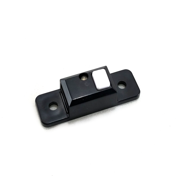
A moving part has an end point it can go to. When an arm comes all the way down, or a mechanism reaches the end of its travel, the motor pushing further can damage the parts. One way to know that the part has reached that point is a limit switch. This button-like part is placed at the end point, and the moving part presses the switch when it gets there.
The information the switch gives is whether it is pressed or not. The program decides what to do with this information. While the switch is pressed, the program can hold back the command that moves the part further and allow it to move away in the opposite direction. So it is not the switch itself that blocks the motion, it is the software that reads that information.
Knowing that you have reached the end point is one need. Knowing how far the part has moved between the two ends is another need, and it calls for another kind of measurement.
Encoder
An encoder is a part that measures the rotation of a shaft. When the properties of the motor and the mechanical transmission in between are known, this measurement can be related to how far the mechanism has moved. The shaft's rotation is not the same thing as a ready-made arm angle or the robot's place on the field; it is still the program that makes the link between them.
The measurement starts from somewhere. If you have a known starting point, you can track the motion after it. A limit switch can be used to set this starting point: when the part reaches the end, the spot it is in becomes a known point.
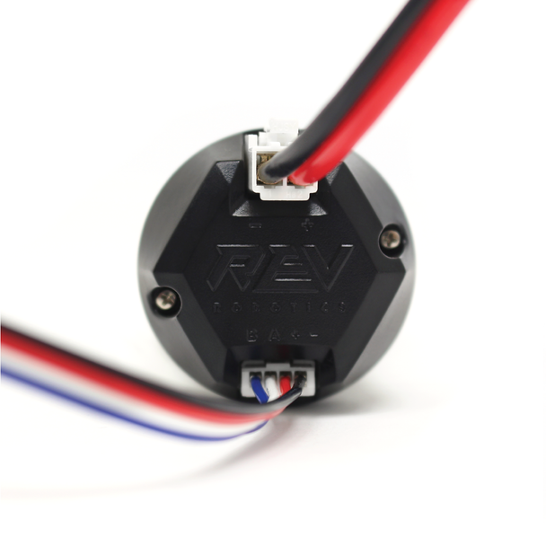
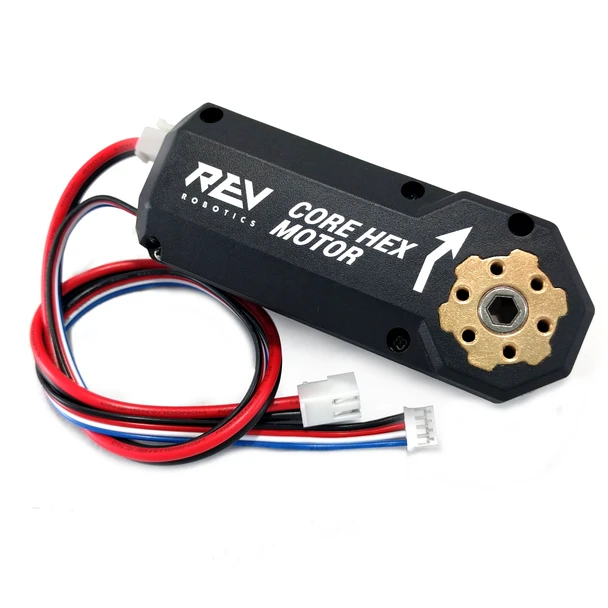
In motors that are common in FTC, such as the REV HD Hex, REV Core Hex and goBILDA Yellow Jacket, the encoder is inside the motor. The motor has two connections with separate jobs. On the power side, two wires carry the electricity that turns the motor. On the encoder side, four wires carry the measurement information. Depending on the motor model, these connections can be fixed cables or sockets.
You can give a motor a power command without reading the encoder, and the motor will still turn. The encoder stays separate from the connection that supplies power and does the measuring job. The program can use this measurement to control how far the mechanism moves, so it goes as far as you want.
Deadwheel and odometry pod
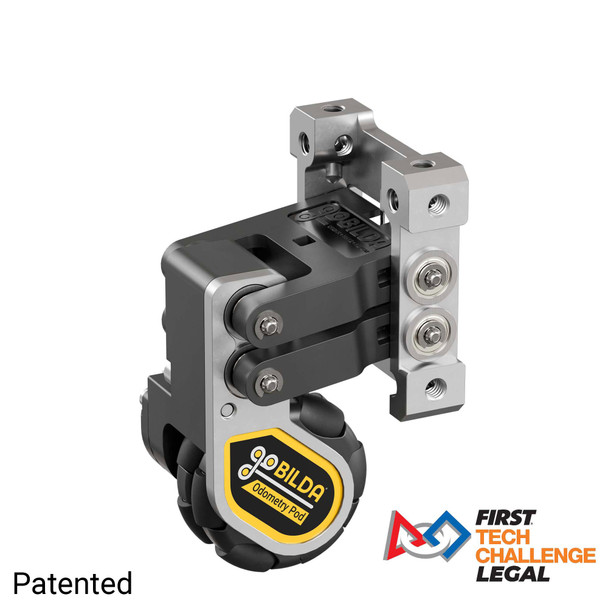
The encoder on the motor's shaft measures that shaft's rotation. For the chassis, this measurement does not always tell you how far the robot has traveled. When a drive wheel slips on the floor, or spins for a moment without touching the ground, the motor keeps turning but the robot does not cover as much ground as you expect.
For this, a separate tracking wheel that does not drive the robot is used. This wheel is not connected to a motor; it rolls along the floor on its own as the chassis moves. In English sources it is called a deadwheel. The wheel's own encoder measures its rotation, and the rotation of a wheel that does not slip tells you more closely how far the robot has really traveled. This measuring unit, made of the tracking wheel, the encoder and the mount that attaches them to the robot, is called an odometry pod.
On goBILDA's pod product, the spring in the mount presses the wheel down toward the floor and helps keep contact. If the robot lifts off the ground, or the wheel rides over an obstacle, the measurement can still go wrong.
The pods' measurements help you track where the robot is going, especially in the Autonomous period. Because a chassis with mecanum wheels can also slide sideways, this tracking is extra useful there. You do not need to add pods to drive a mecanum chassis.
Gyro and IMU
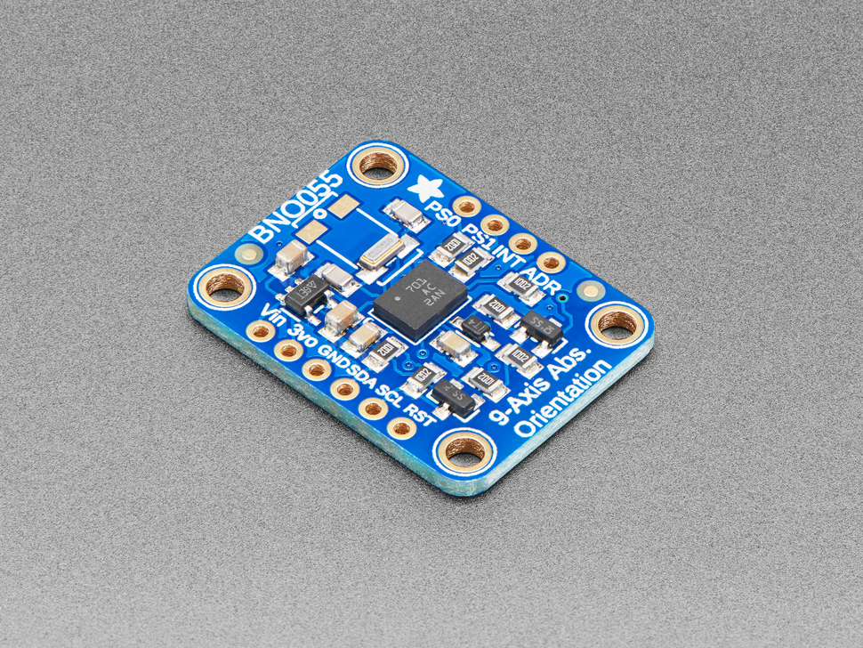
A robot does not only go forward and backward; it also turns in place. In the back seat of a car, even with your eyes closed, you can feel the car going into a curve, because the balance organ inside your ear senses the turning motion. A gyro is a sensor that does a similar job for the robot. It measures that the body is turning and how much it turns, and the program uses this measurement to track how much the robot's heading has changed.
A gyro is usually not on its own. It sits together with other motion sensors inside a unit called an IMU. There is also an IMU inside the Control Hub, so you may not need to buy a separate gyro product for your robot.
We have met the parts that measure how much the wheels turn and the part that measures the body's rotation. There is also a product that combines these two pieces of information.
Pinpoint
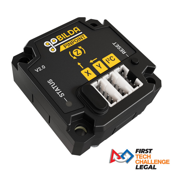
The goBILDA Pinpoint is an odometry computer that processes the measurements connected to it. It combines the measurements of two pod encoders with the measurements of its own built-in IMU. In the common layout, one pod tracks the robot's forward and backward motion, and the other tracks its sideways motion.
As a result of this combining, the Pinpoint sends the robot's position and heading estimate to the Control Hub, and your program can use this estimate. The estimate is calculated from the point where the robot started. When the robot is switched on, it does not know by itself where it is on the field.
Distance, color and camera
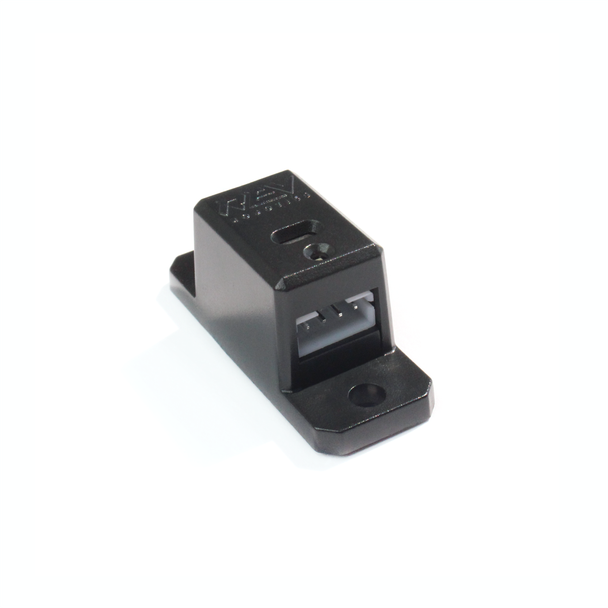
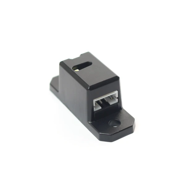
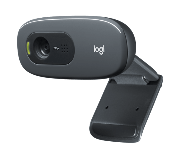
You can also measure things around the robot. A distance sensor measures how far away the surface in front of it is. A color sensor measures the color of a surface close to it. A camera takes images, and by processing these images the robot can tell game pieces or markers on the field apart.
You can think of the sensors we met in this lesson as the robot's sense organs. Whether the information they measure turns into useful motion depends on how they are used in the program. We look at the tools we use to write the program in the 0.9 Software lesson.
Extras
- REV motors shows the motors used in FTC and their connections.
- REV servos explains the types of servos and how they are used.
- goBILDA Servo Programmer is the board's product page; the compatible servos are listed here.
- REV robot battery is the product page of the robot's main battery.
- REV Driver Hub is the product page of the driver device and its own battery.
- REV Control Hub basics gives the board's operating voltage and basic features.
- Series and parallel battery configurations explains how cells are connected in battery packs.
- FTC Docs control system explains the parts of the control system all in one place.
- Control Hub ports is the list of connections on the hub.
- REV limit switch and digital sensors is the page to check for connecting a switch.
- REV motor encoders explains the encoders inside motors.
- goBILDA odometry pod is the pod product's page.
- goBILDA Pinpoint is the product page of the odometry computer.
- FTC Docs sensors and IMU is the list of sensors used in FTC.
- Placing the electronics on the robot and its cables is covered in the 1.2 Electronics layout and cables lesson.
- Powering up the robot for the first time and updating the devices is covered in the 1.3 First power-up and device updates lesson.
- Connecting to the robot with the driver device is covered in the 1.4 Connecting to the robot lesson.
- Setting up the motors in the software is covered in the 1.5 Motor configuration lesson.
- Your first motor program is in the 1.6 First motor program lesson.
- Controlling a motor with a gamepad is in the 1.7 Motor control with a gamepad lesson.
- We will look at practice with the limit switch, position control with an encoder, pods and Pinpoint in later units.
- Resources and printables