0.7 Introduction to mechanical parts
Being written
This page is being written and will be updated again on 30 September 2026. For now comments are collected on the Turkish version of this page (language menu): if you find something missing or wrong, you can write it there. The feedback we receive decides what changes in this round.
What you learn in this lesson
What structure holds the robot's parts? How is a turning part attached to the robot? How does motion get from the motor to somewhere else?
On an FTC robot, wheels turn, arms lift and motors run. All of them are attached to something, and the parts that make those connections have names. This page does not teach you how to build a robot. We get to know the robot's mechanical parts by seeing what need each one is used for.
Profiles and plates
As the robot moves on the field, it gets shaken, bumps into other robots, stops and starts again. To keep the motors, wheels, battery and the rest of the robot in place, you need a strong structure that carries them all. The first version of this structure that comes to mind is metal bars attached to each other.
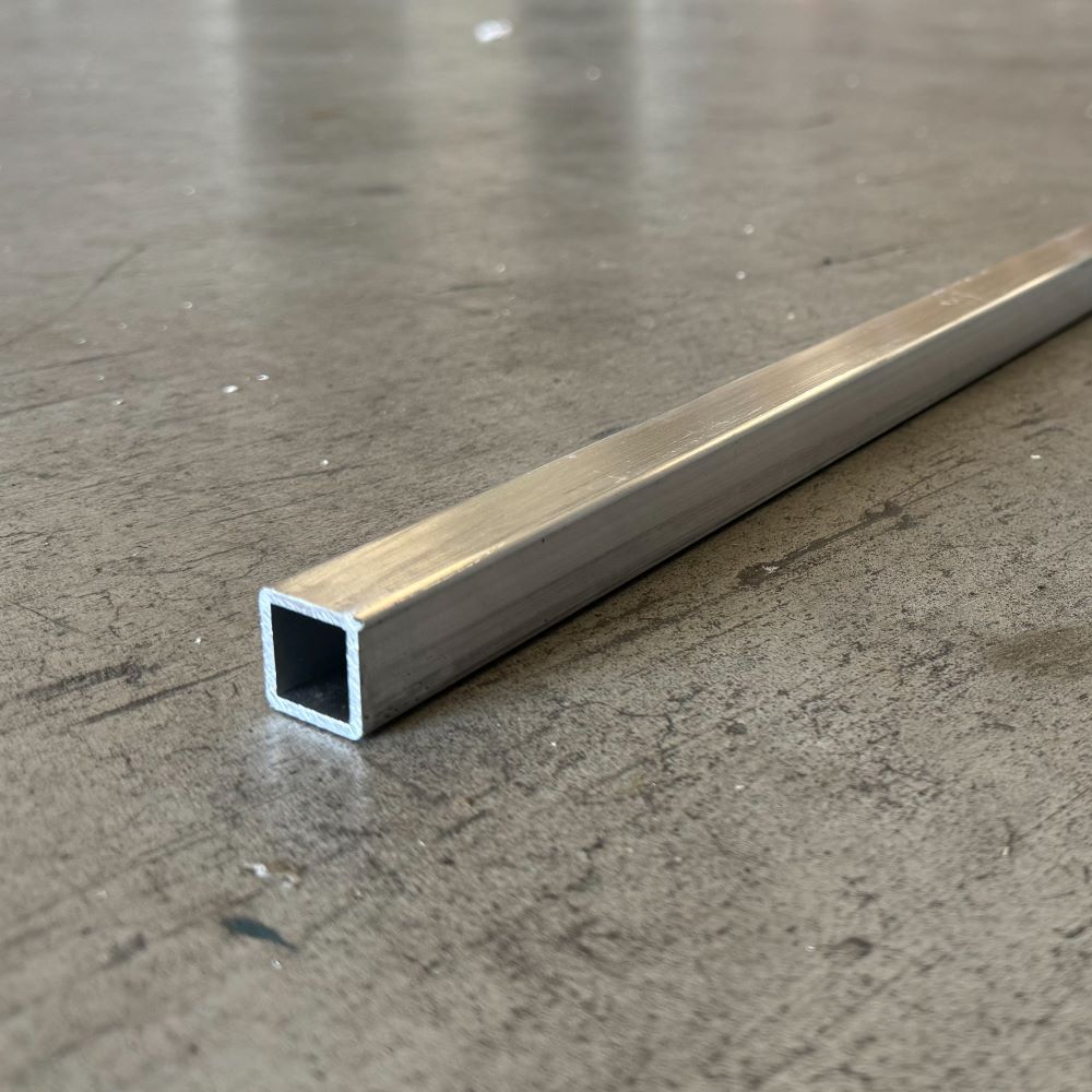
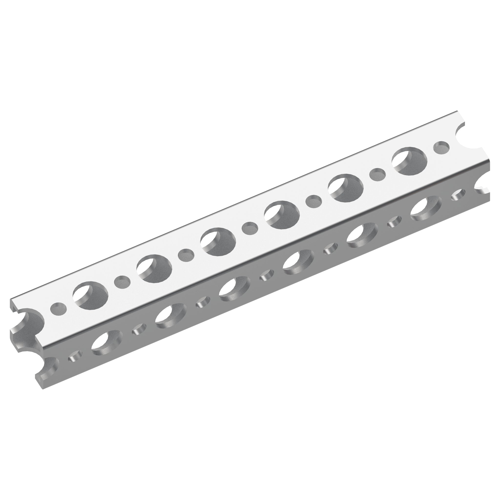
A solid metal bar is strong, but it is heavy. The heavier the robot gets, the harder the motors have to work to move it. If a part that looks the same size from the outside is left hollow inside, it has less metal in it and gets lighter. When you look at it from the end, you see the hollow in the middle. A structural part with this shape is called a box profile. Not every structural part is like this, and not every part you hollow out stays just as strong. The point here is not to carve out a part yourself, but to understand why ready-made profiles are sold in this shape.
A profile does nothing on its own. You attach parts to it. To fasten a motor, a wheel mount or a holder to a profile, you need a hole for a bolt to go through. The profiles used in FTC are usually sold with holes along their whole length. That way you can attach a part anywhere you want on the profile, using the holes that are already there.
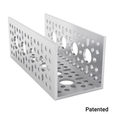
You cannot get your hand or your wrench inside a closed profile. That becomes a problem when you need to hold the nut on the end of a bolt or place a part inside. In profiles with one face left open, the inside is within reach of your hand and your tools. Parts that look like the letter U when you view them from the end are called U-channels, and ones whose edges curl inward are called C-channels.
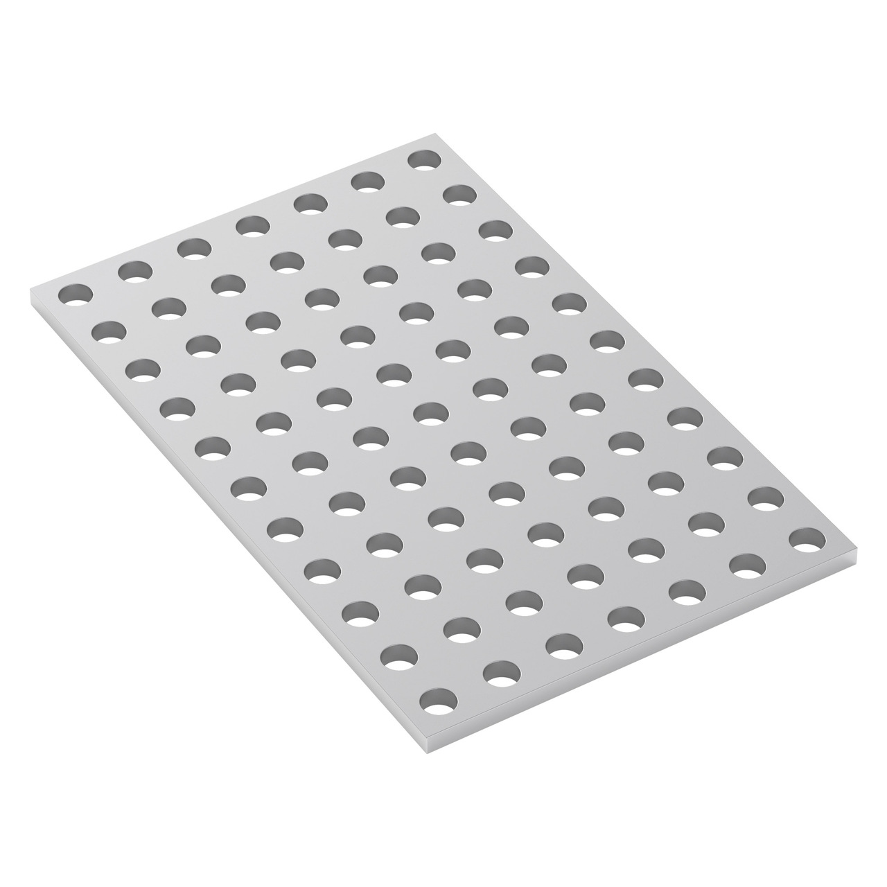
In some places you want a flat surface, not a bar. For the spot where the battery, the control boards or a mechanism will sit, you use metal sheets with holes, called plates. You can find all the parts you have met so far under the structure heading in manufacturers' catalogs. Manufacturers such as goBILDA and REV have their own connection families, and their sizes and hole patterns can differ from each other. We will look at what to buy from which manufacturer in the 0.10 Sourcing lesson.
Bolts, nuts and angle brackets
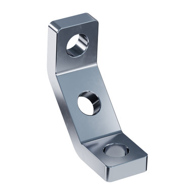
To join two parts, you line up their holes. A bolt goes through both holes, and when the nut on the back is tightened, the two parts hold onto each other. Bolts and nuts are parts you see in everyday life too. What is different on a robot is that their sizes and counts are specific.
If two profiles meet at a corner, a bolt cannot hold them directly, because their holes do not face the same way. A connecting part goes in between. An angle bracket is a part with two faces pointing in different directions. One face is bolted to one profile, the other face to the other profile. That way the two profiles stay at a right angle to each other and keep that angle.
Shafts and hubs
The job of structural parts is to stay in place. The job of a wheel is to turn. If you clamp a wheel tight to a profile, it stays in place but it cannot move the robot. You need a metal bar that goes through the center of the wheel and can turn together with it. This bar is called a shaft. Not every wheel on a robot is attached this way, but this is the common way to attach drive wheels.
A shaft going into a hole is not enough to turn that part. If you pass a round bar through a round hole that is loose on it, the bar spins inside the hole and the part stays where it is. The solution is in the shape of the shaft. If you cut a bar straight across and look at the cut surface, the shape you see is called the cross-section. A round bar has a circular cross-section. The shafts used with FTC parts have six flat faces and six corners, so their cross-section is a hexagon. These shafts are also called hex shafts, since hex means hexagon. When the hole in the middle of the part is also a hexagon, the flat faces of the shaft press against the edges of the hole, and the part has to turn together with the shaft.
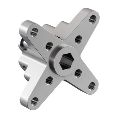
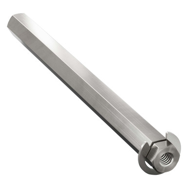
This is not the only way to attach a part to a shaft. A hub is a separate part that connects the shaft and the part being attached to it. The hole in its middle slides onto the shaft, and a wheel, a gear or another part is bolted to its wide face. A hub lets you attach a big part to a thin shaft and choose where the part sits on the shaft. On round shafts, clamping connections tightened with a screw are used so the hub grips the shaft.
Not every shaft of the right length fits your part, because the shape and size of the shaft must also fit the part's hole. REV DUO parts are built around a 5 mm hex shaft. goBILDA uses 8 mm REX shafts. The corners of this shaft are rounded, so you cannot assume it fits a hexagonal hole. The number of millimeters in the product name is not enough information on its own. When you buy a shaft and a part together, you need to check the manufacturer's dimension drawing and see that both the shape and the size match.
Bearings, spacers and shaft collars
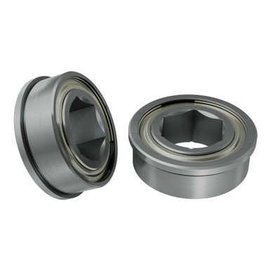
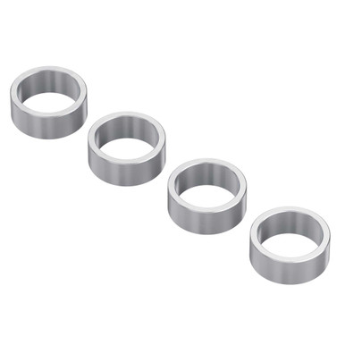
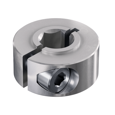
The turning shaft also needs to sit somewhere in the robot's structure. If you jam the shaft into a hole in a profile, it stays in place but cannot turn. A bearing meets both needs at once. Its outer side sits in a seat in the profile and stays put, and its inner side slides onto the shaft and turns with it. Between the two sides are rows of balls, which reduce the friction created while turning.
The shaft turns inside the bearing, but the parts on it can still rub against each other and against the profile. If the wheel touches the profile, it gets harder to turn. The short tube-shaped parts placed in between are called spacers. A spacer slides onto the shaft and fills the gap between two parts, setting the distance between them. A spacer does not need to grip the shaft, and the shaft can turn inside it.
What is left is the shaft and the parts on it sliding along its length. A shaft collar, or just collar, is a ring that slides onto the shaft and is tightened with the screw on its side. It grips the shaft where it is tightened. When the shaft starts to slide in that direction, the collar presses against the bearing or spacer in front of it and stops the shaft. A collar floating in the air cannot do this on its own. It needs a part to rest against. These three parts each do a different job. The bearing lets things turn, the spacer puts distance in between, and the collar limits sliding.
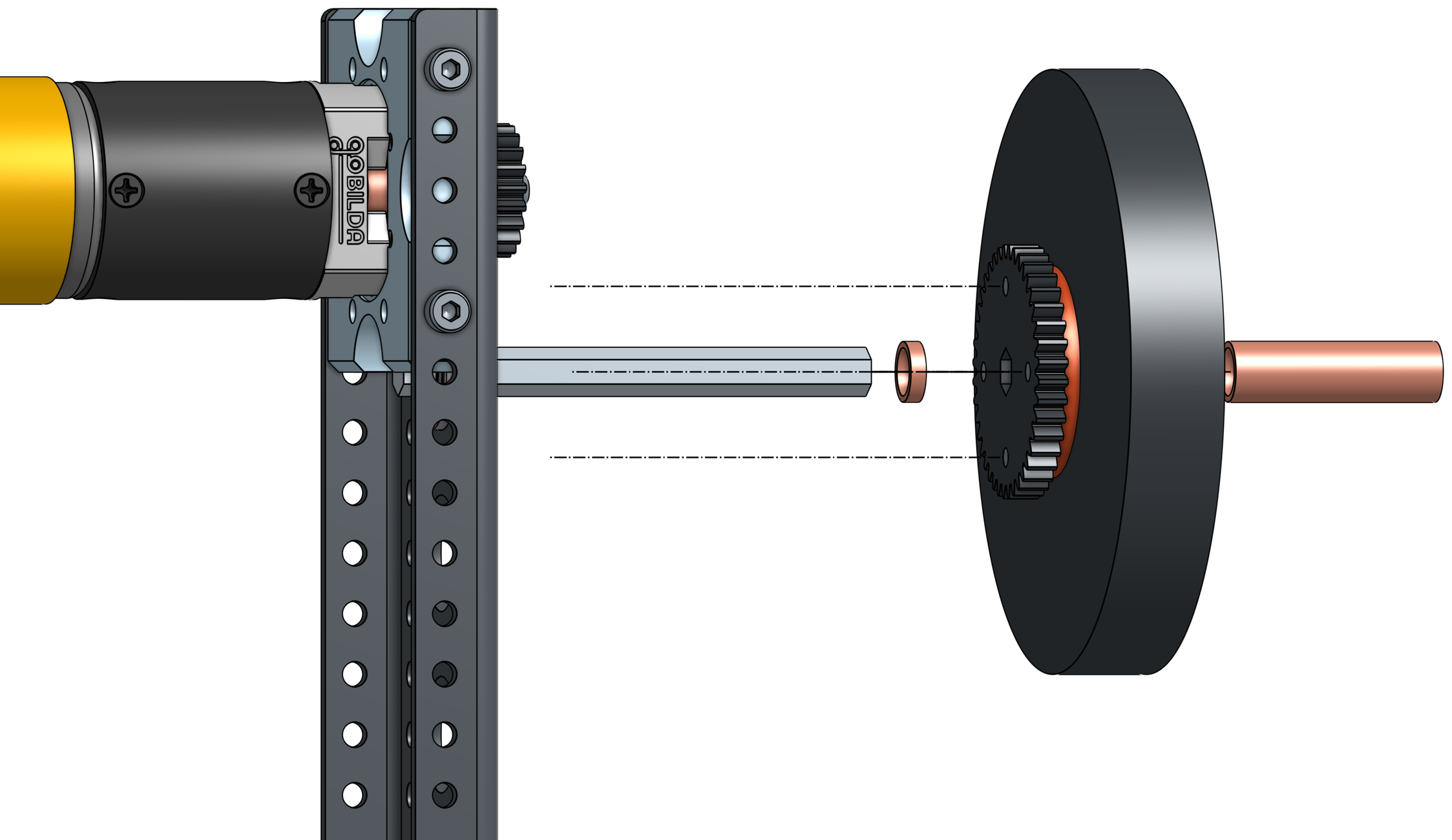
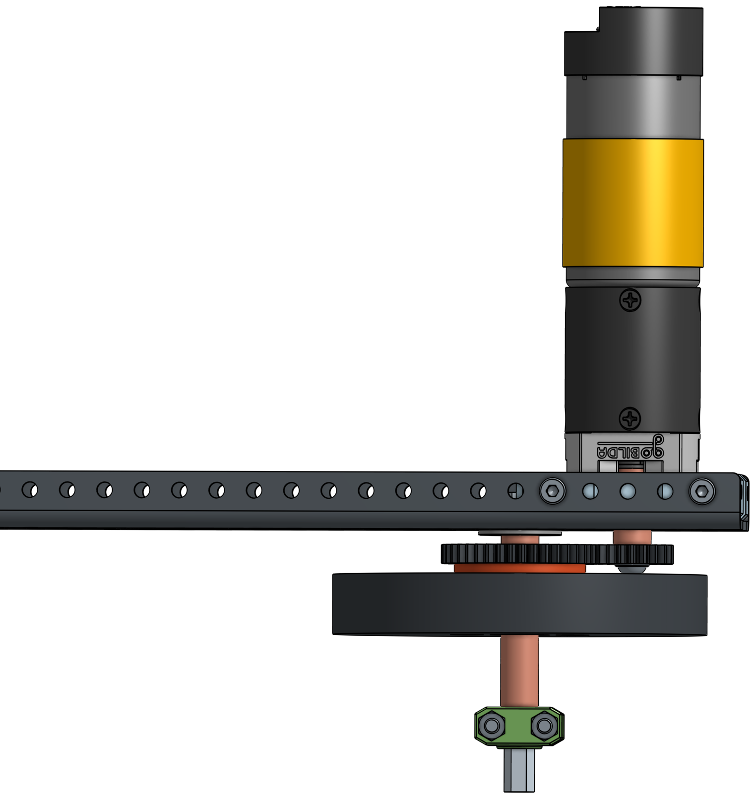
All of these parts come together on a single shaft. In Probot Studio's Omni Chassis kit, the drive shaft goes through the bearing in the profile, and first the spacers, then the gear and the wheel go onto it. The shaft collar keeps this group in place. The parts you have met one by one finally come together like this.
Wheel types
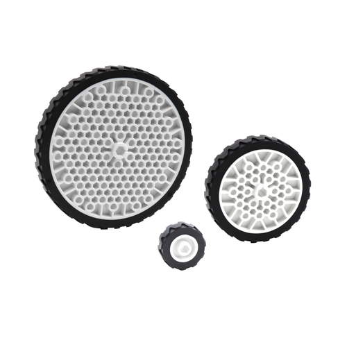
Now for the wheel on the end of the shaft. If the surface of the wheel that touches the ground is made of rubber, it grips the floor, and the wheels hold their direction as the robot drives forward and back. These wheels are called traction wheels.
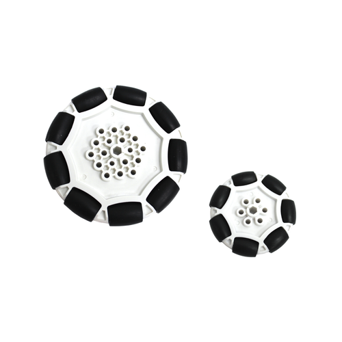
Some wheels have small cylinders lined up around their edge. These cylinders, which can spin freely on their own axes, are called rollers. While the body of the wheel turns with the shaft, the rollers can also spin on their own. When you set the rollers perpendicular to the direction the wheel turns, the wheel rolls forward and back normally, and when it is dragged sideways, the rollers spin and reduce the resistance. These wheels are called omni wheels.
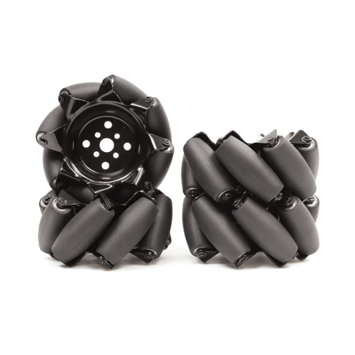
A mecanum wheel also has rollers, but they sit at an angle to the wheel's axis. When four mecanum wheels are mounted in the right layout and turned in the right directions, the robot can move sideways. A single mecanum wheel cannot do this on its own. What creates the motion is the work of the four wheels together. Drive layouts and how these wheels are controlled are a separate topic. We will look at them in Unit 1 while building a chassis.
The Omni Chassis uses both types together. At the back, two rubber drive wheels drive the robot, and at the front, two omni wheels slide sideways when it turns.
Motor
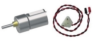
The shaft, bearing and wheel make a setup that can turn. This setup does not turn by itself. The part that provides the motion is the motor. The motor's body is fixed to a profile and stays in place, and the shaft coming out of its end turns when electricity is applied.
If the part you want to turn is right in front of the motor and the connection fits, you can attach the part directly to the motor's shaft. It is not always like that. The motor may sit somewhere else inside the robot, the shaft you want to turn may be far away, or you may want a speed different from the one the motor turns at. In these cases you need parts that take the motion from the motor and carry it to another shaft.
Where you power the motor from and how you turn it with a program is the topic of the 0.8 Introduction to electronic parts lesson.
Gears and gearboxes
The shaft at the end of a motor turns at a certain speed, and at that speed it turns with a certain force. Not every mechanism on the robot wants the same balance. You want the wheels to turn fast, and a heavy arm to lift slowly and strongly. When gears are put in between, the speed and the turning effect that reach the mechanism change. The slower output can turn a heavier load, and what makes this possible is not the motor itself but the gear transmission.
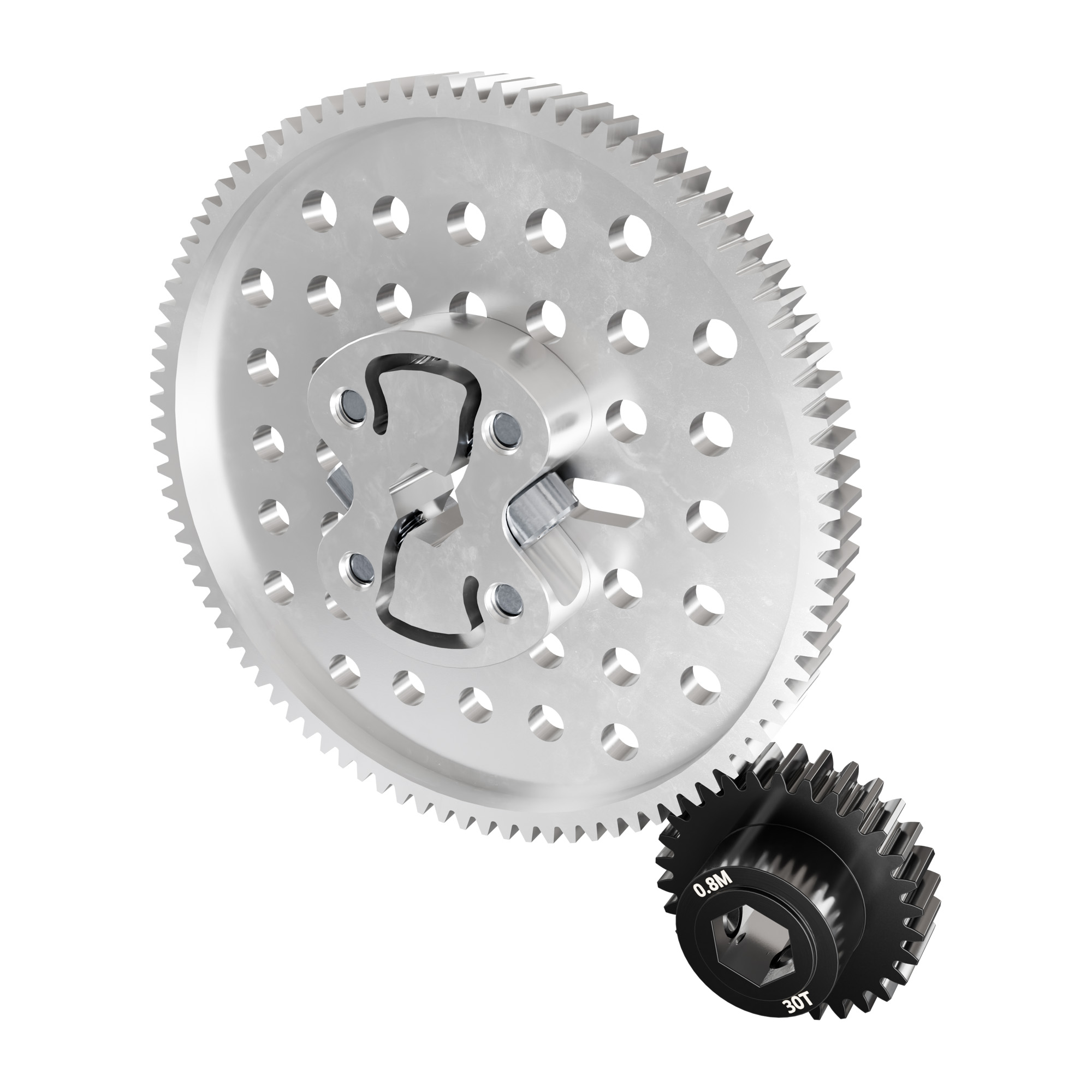
A gear is a wheel with teeth cut into its edge. When the teeth of two gears mesh, one turns the other. If their tooth counts are different, the turning changes too. When the gear on the motor side is small and the one on the mechanism side is big, the mechanism turns more slowly and can turn a heavier load. When you set it up the other way around, the mechanism speeds up and the load it can turn gets smaller. The motor's own turning does not change. What changes is the speed and force that reach the mechanism.
You can see gears out in the open on a robot. The same job may also be done inside the motor itself. Most motors used in FTC have a closed box on their end, with small gears meshed together inside. This box is called a gearbox.
The gears inside the gearbox do the same job we just described. The shaft inside the motor turns fast, and the shaft coming out of the gearbox turns more slowly and can turn a heavier load. The motor and the gearbox are often sold together and look like one part from the outside.
For two gears to work together, their teeth need to be the same size. The measure that describes the size of a tooth is called the module. Two gears with different modules do not work together, even if their tooth counts are suitable. Being the same module is not enough on its own either. The shape of the teeth also has to match. When you build a robot, this means that when you choose a gear for a mechanism, you check its module as well as its tooth count. MOD 0.8 is a common value for goBILDA gears. In REV DUO, plastic gears can be MOD 0.75 and metal gears MOD 0.8. Two parts coming from the same brand does not mean they will fit together. You can check the module value on the product page.
Belts and pulleys
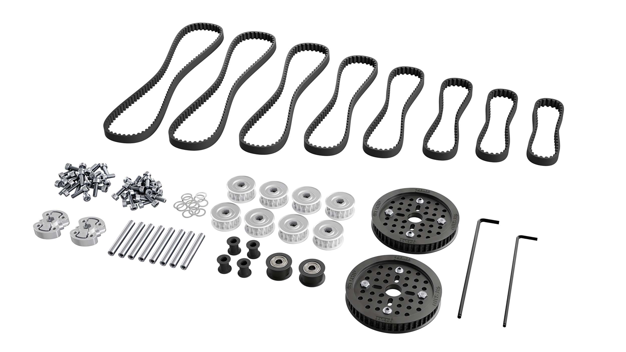
A motor cannot always sit next to the mechanism it will turn. The robot's arm may be up high while the motor that turns it is down low. On FTC robots, a belt is the most common way to carry motion to a distant mechanism. A pulley is mounted on each of two shafts, and a belt runs between the pulleys. When the motor turns its own pulley, the belt carries the motion to the other pulley.
The belt has teeth on its inner surface, and these teeth sit in the grooves on the pulley. Because the motion is passed on by the teeth pushing each other, not by friction, the belt does not slip on the pulley.
Belts differ from each other in a few ways. A closed belt is shaped like a loop and runs between two pulleys. An open belt has free ends. It is cut to the length you want, and its two ends are attached to the part that will move. Every belt has a width, and it needs to match the width of the pulley. The length of a closed belt is usually given by the number of teeth on it. The shape of the teeth also varies. HTD and GT2 are two of the tooth profiles you will come across. The belt and the pulley need to have the same tooth profile. goBILDA and REV sell their own belt and pulley families, and if you stay within one family, these sizes fit each other.
Chain and sprockets
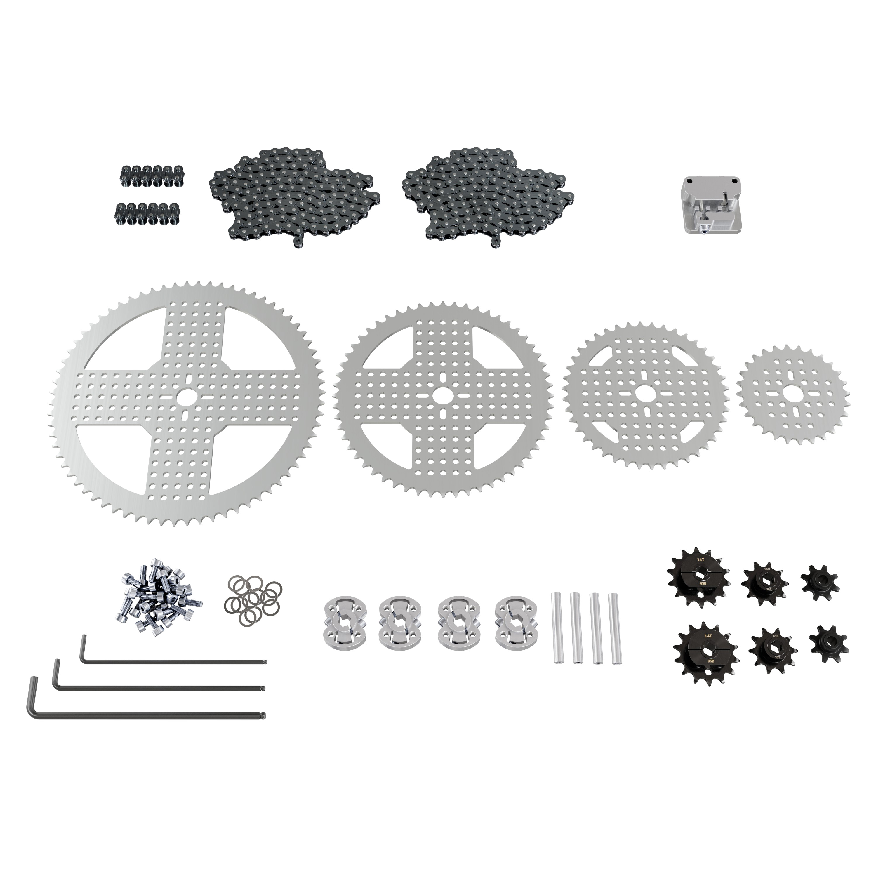
Between two distant shafts, a chain can also be used instead of a belt. A chain is made of links joined together, and it works with a sprocket, whose teeth sit in the links. It is a smaller version of the setup you see on a bicycle. It can be used to turn the robot's arm or another mechanism that sits far away. A chain is not an advanced version of a belt. It is a different answer to the same need.
Getting parts
You can get some of these parts from FTC manufacturers, and some from industrial suppliers near you. Belts and bearings are sold at shops that sell belts and bearings. When you go, you need to state the belt's type, tooth pitch, width and length. You can find the hex shafts, hubs, gears and structural parts used in FTC in the Probot Studio store, and you can also reach other FTC manufacturers in Türkiye. You can also make pulleys and gears yourself with a 3D printer. In that case, the print material and the shape of the part affect how strong it is. In places that carry heavy loads or take hits, metal gears may be the better choice, and REV and local manufacturers are options for this. We take a wider look at what to get from where in the 0.10 Sourcing lesson.
All the parts here carry motion. We will meet the motor that starts the motion, and the electronics that run it, in the 0.8 Introduction to electronic parts lesson.
Extras
- The ReCalc gear calculator gives the distance between the centers of two gears' shafts. The tool asks for the tooth size as DP, not as module. The DP value is 25.4 divided by the module, so for MOD 0.8 gears you enter 31.75.
- The ReCalc belt calculator works out the belt length from the pulley tooth counts and the center distance. The product list it shows is not a shopping recommendation.
- The goBILDA HTD 5 mm belt and pulley page shows the lengths you can buy when working with goBILDA parts.
- The gm0 belt page explains belt types and the measurements for choosing one.
- The REV DUO shaft page shows REV's family of shafts, spacers and collars.
- The gm0 gear page is a detailed source for gear sizes and center distance.
- Resources and printables